semi合集-English.pdf - 第6449页
SEMI G76-0299 © SEMI 1999 5 8.4 Dimension Test Procedure 8.4.1 Thickness (1) Equi pment — Use a m icrometer standardized to JIS C-2318 or equivalent. (2) Material — Use the TCP polyim ide adhesive tape as received from t…
SEMI G76-0299 © SEMI 1999 4
6.8 Appearance and Defects — See Table 8. Width and thickness for the base film, adhesive material and cover
film are not particularly specified.
Table 8. Appearance and Defects
Item Test Method Unit Value
MD Curl 8.8.1 mm
< 15
TD Curl 8.8.2 mm
< 6
Wakame 8.8.3 Number/m
< 20 of < 2 mm, 0 of > 2 mm
Camber 8.8.4 mm/m
< 1
Twist 8.8.5 Degrees
< 135
Defect 8.8.6 #/m or #/100m
< 5/m between 0.1 mm
2
and 1mm
2
or, < 10/100 m of > 1 mm
2
7. Sampling
A sampling plan shall be defined between the user and
supplier.
8. Test Methods
8.1 Test Conditions
8.1.1 Normal — Normal condition refers to a
temperature of 23 ± 5°C, and relative humidity of 55 ±
15%.
8.2 Materials
8.2.1 Material Preparation — Unless otherwise
specified, take the needed length of material from the
inner part of the roll after peeling off the first three
layers.
8.2.2 Lamination — Use the following steps to
prepare materials which require lamination:
(1) Material — Unless otherwise specified, use a
copper foil which has previously been decided
upon by the user and supplier.
(2) Lamination Method — Unless otherwise
specified, a method used shall be agreed
between user and supplier.
(3) Curing — Unless otherwise specified, a method
used shall be agreed between user and supplier.
8.2.3 Etching — For material which requires etching,
unless otherwise specified, a method used shall be
agreed between user and supplier.
8.2.4 Plating For material which requires plating,
unless otherwise specified, a method used shall be
agreed between user and supplier.
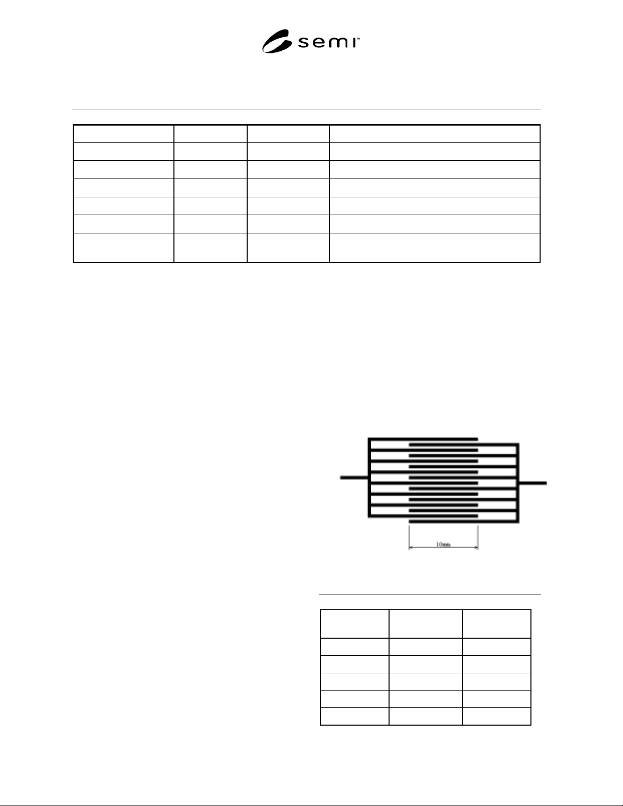
8.2.5 Test Pattern — The pattern used in Figure 1 is
recommended for the shape and dimensions of the test
pattern. Where this is not applicable, a pattern used
shall be agreed between user and supplier.
8.3 Pre-Conditioning — Unless otherwise specified,
leave the sample materials in normal condition for 24 ±
4 hours.
Figure 1
Test Pattern
Table 9. Test Pattern
Line Pitchs
(
µ
m)
Line Widths
(
µ
m)
Line Spacings
(
µ
m)
90 45 45
70 35 35
60 30 30
50 25 25
40 20 20

SEMI G76-0299 © SEMI 1999 5
8.4 Dimension Test Procedure
8.4.1 Thickness
(1) Equipment — Use a micrometer standardized to
JIS C-2318 or equivalent.
(2) Material — Use the TCP polyimide adhesive
tape as received from the supplier.
(3) Measurement — Measure the center, and 3
points at least 1m apart in the MD direction,
and calculate the average.
8.4.2 Width
(1) Equipment — Use a projector capable of
reading a minimum of 0.001 mm integrals.
(2) Material — Use the TCP polyimide adhesive
tape as received from the supplier.
(3) Measurement — Measure the TD direction
length in 3 points at least 1m apart in the MD
direction, and calculate the average.
8.5 Mechanical Efficiency Tests
8.5.1 Copper Foil Adhesive Strength
(1) Equipment
(a) A pull tester with an appropriate
measurement range, having a tolerance of ±
5% of the indicated value, and capable of
maintaining a cross-head speed of 10−50
mm/min.
(b) A pull tester with a sample retention heating
device or sample chamber for retaining
surface temperature for measuring conditions.
(2) Material
(a) Normal Use a sample with copper etching
and conductor width of 50 ± 10 µm and
conductor length of more than 30 mm. The
measurement direction and number of
samples should be previously determined by
the user and supplier. Unless otherwise
specified, use 2 samples and measure in the
MD direction.
(b) Heated Use the same as (a), except with a
conductor width of 2 ± 0.5 mm.
(3) Measurement
(a) Normal After measuring the sample
conductor width, fix the sample in the pull
tester. In order to keep peeling angle at 90°,
affix a reinforcement panel with double-
sided adhesive tape. Pull and peel off more
than 20 mm of copper foil at a speed of 10
mm/min
-1
and an angle of 90 ± 5°. Measure
the load during this interval.
(b) Heated Fix the sample in retention heating
device of the pull tester and raise the
temperature, or, fix the sample in a
previously retention heating device in the
pull tester. It is also feasible to use a sample
chamber which can heat the whole sample.
Measure the sample surface temperature
with a contact surface thermometer, and
when a temperature of 150 ± 5°C is
confirmed, quickly pull and peel off more
than 20 mm of copper foil at a speed of 10
mm/min
-1
and an angle of 90 ± 5°. Measure
the load during this interval.
(c) Soaked in Solvent After soaking the
sample in a specified solvent at 23 ± 5°C
for 5 minutes, remove the sample and rinse
and dry off solvent thoroughly. Place in
normal conditions, as described in Section
8.1.1, for 24 ± 4 hours and perform the
same test as above " normal" (3)(a).
However, if the solvent is inorganic, wash
sample well with water after taking it out
of the solvent and dry at 80 ± 5°C for 30
minutes. Then place in normal conditions,
as described in Section 8.1.1, for 24 ± 4
hours and perform the same test as above
" normal" (3)(a). The type and condition of
the solvent used shall be agreed between
the user and supplier.
(4) Calculation
(a) Compile the measurements, leaving out the
overshoot at the beginning and end, and
calculate the average of samples with a
stable section of 10 mm. The method of
calculating the average should be
predetermined by the user and supplier.
Unless otherwise speci-fied, place a ruler
over the chart and determine visually.
(b) Calculate the load on pulling and peeling
off of each sample, excluding the samples
conductor width, and the average will be
the copper foil adhesive strength.
8.5.2 Cover Film Release Strength
(1) Equipment Use the same equipment as in
Section 8.5.1 (1).
(2) Material Use a 250 mm section cut from the
TCP polyimide adhesive tape as received from
the vendor.
SEMI G76-0299 © SEMI 1999 6
(3) Measurement After measuring the sample
cover film width, fix the sample in the pull
tester. In order to keep the sample at 90°, affix
a reinforcement panel with double-sided
adhesive tape. Pull and peel off more than 50
mm of cover film at a speed of 50 mm/min
-1
and an angle of 90 ± 5°. Measure the load
during this interval.
(4) Calculation Use the same method as Section
8.5.1, (4).
8.6 Electrical Efficiency Test
8.6.1 Volume Resistivity
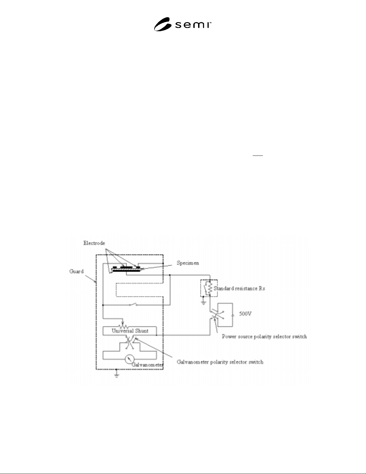
(1) Equipment Use high insulation-resistance
meter which conforms to JIS C-1303, or
similar resistance measuring device (see
Figure 2).
(2) Material - Prepare a section of TCP
polyimide adhesive tape with adhesive
material width of more than 50 mm, laminate
with copper foil and cure according to the
method described in Section 8.2. In addition,
etch the main electrode and guard electrode
into the shapes found in Figure 3. For the
counter electrode, melt on a conductive
material to the opposing polyimide film
surface, or form it out of conductive paste. Dry
these at 80 ± 5°C for 30 minutes. Cut these
into 50 mm squares for the material.
(3) Measurement Use the following steps to
measure under normal conditions: Measure the
thickness of the samples in units of 0.1 µm,
and measure the inner diameter of the gap in
the circular upper electrode in units of 0.05
mm. Apply direct voltage of 500V ± 5V, and
measure the resistance value after 1 minute.
(4) Calculation Use the equation below.
)/(
4
1
cm
t
D
Rvv Ω×=
π
ρ
Where ρv is volume resistivity, Rv is resistance
value, t is sample thickness, π is pi, and D
1
is main
electrode outer diameter.
Figure 2
Resistance Measurement Device for Volume Resistivity