semi合集-English.pdf - 第3894页
SEMI F28-1103 © SEMI 1997, 2003 4 Figure 1 Panel Test Apparatu s 6.2.11.4 The s pool pie ce is to be installed when t he test stand i s not in use. A contin uous low flow is t o be maintained t o purge the system. The pa…

SEMI F28-1103 © SEMI 1997, 2003 3
(≥ 0.02 µm) per cubic foot of test gas under test
conditions.
6.2.3 Pressure Regulator — Pressure regulators are
required to maintain system test pressures.
6.2.4 Pressure Gauge — Pressure transducers or
gauges are required to monitor system test pressures.
6.2.5 Flow Control Device — A 0–100 slpm flow
control device is required for controlling the test flow
rate.
6.2.6 Tubing — A 6.35 mm O.D. × 0.89 mm wall (1/4"
O.D. × 0.035" wall) tubing is required. The tubing
shall have an average surface roughness of 0.25
micrometer (10 microinch) Ra or less. Electropolished
tubing (as defined in SEMI F16) is recommended.
6.2.7 Sampler — The sampling system consists of a
diffuser equipped with a pressure reducing device (e.g.,
critical orifice) and a sample probe. All parts of the
sampling system are to be electropolished with a
surface roughness of 0.25 micrometer (10 microinch)
Ra or less. If a critical orifice is to be used for pressure
reduction, it is not required to be electropolished. The
diffuser and sample probe must be sized to obtain
isokinetic sampling at the specified test conditions. The
critical orifice must be sized to obtain the specified
panel pressure at the specified test flow rate.
6.2.8 Spool Piece — Spool pieces shall be electro-
polished 316L stainless steel tubing with a surface
finish of 0.25 micrometer (10 microinch) Ra or better.
The spool piece is to be installed in the system in place
of the test device while obtaining background counts
for the system.
6.2.9 Fittings — Use face seal connectors or
compression fittings depending on test panel end
connections.
6.2.10 Gaskets — Use non-plated metal gaskets where
required.
6.2.11 A CNC capable of detecting particles at least as
small as 0.02 µm at a 50% efficiency envelope as
defined by ISO 14644, with a sampling flow rate of
1.23 SLPM (0.05 scfm) or greater, is to be used for
particle counting. A laser particle counter, capable of
detecting particles at least as small as 0.1 micro meters,
may be used in addition to, or in place of, the CNC.
Test durations in this test method have been established
based on a sampling flow rate of 1.23 SLPM (0.05
scfm).
6.2.11.1 Instruments should be calibrated regularly,
according to manufacturer’s recommendations. For the
CNC, this includes routine checks of sample flow rate,
working fluid level, and zero.
6.2.11.2 The CNC and data collection equipment
should have power surge suppression.
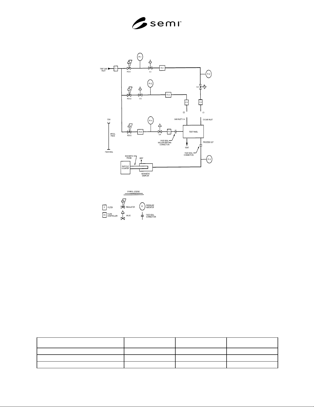
6.2.11.3 Setup and Schematic — See Figure 1.
SEMI F28-1103 © SEMI 1997, 2003 4
Figure 1
Panel Test Apparatus
6.2.11.4 The spool piece is to be installed when the test stand is not in use. A continuous low flow is to be
maintained to purge the system. The particle counter may be turned off. For an extended shutdown, the system
(excluding the CNC) should be pressurized and capped.
6.2.11.5 After initial construction, the spool piece should be installed and the system should be cleaned up by
running a high-flow rate of test gas (> 60 SLPM) and gently tapping all components (except the CNC) downstream
of the final filter. This procedure should be followed by a start-up phase which characterizes system cleanliness by
conducting the entire test protocol with the spool piece installed.
6.3 Test Procedures
NOTE 2: Ensure the counter is counting continuously and reporting data each minute. For the duration of the test, the counter
should be continuously counting, except where noted in the test protocol.
6.3.1 This test method classifies panels into three pressure ranges: high, medium, and low. The test pressures and
flow rates for each pressure classification are given in Table 1 below.
Table 1 Panel Test Conditions
Panel Pressure Class High Medium Low
Inlet Supply Pressure 3450 KPa (500 psig) 550 KPa (80 psig) 210 KPa (30 psig)
Panel Outlet Pressure 210 KPa (30 psig) 210 KPa (30 psig) 0 KPa (0 psig)
Test Flow Rate 60 slpm 60 slpm 5 slpm

SEMI F28-1103 © SEMI 1997, 2003 5
6.3.1.1 The test flow rates stated in the above table are
meant to serve as a general guideline. The actual test
flow rates may vary depending on the maximum panel
flow rate as recommended by the manufacturer. The
maximum test flow rate should be the manufacturer’s
maximum recommended flow rate. If no such
maximum flow rate is recommended by the
manufacturer, the flow rates in the above table should
be used.
6.3.2 Background Test — Ensure that all valves
depicted in Figure 1 are in the closed position. Connect
the spool piece to the purge gas inlet (C-2) and the
isokinetic sampler inlet. Ensure that the spool piece and
proper adapters are in place on the test apparatus. (C-1
should be capped at this time.)
6.3.2.1 Close valve V-3. Adjust the regulator (PCV-2)
until PI-5 indicates the appropriate pressure in Table 1.
Open valve V-3 and use FC-2 to establish the specified
test flow rate listed in Table 1. Measure the static
background count. Background count is established
when the counter has sampled a minimum of 74 SL (3
scf), and the arithmetic average during the last 74 SL (3
scf) of gas sampled is < 71 particles/m
3
(< 2
particles/scf). At a sample flow rate of 1.23 SLPM
(0.05 scfm), the time required is one hour. Ensure that
the background counts are stable or decreasing. If
background cannot be achieved after 147 SL (6 scf)
have been sampled, there may be a problem with the
counter or test apparatus.
6.3.2.2 Disconnect the spool piece from C-2 and
connect it to C-1. Cap C-2 at this point.
6.3.2.3 Open valve V-1 and close valve V-2. Adjust the
regulator (PCV-1) until PI-2 indicates the appropriate
supply pressure listed in Table 1. Open valves V-1 and
V-2 to establish flow. Using the flow control device
(FC-1) set the appropriate test flow rate listed in Table
1. Measure the static background count. Background
count is established when the counter has sampled a
minimum of 74 SL (3 scf), and the arithmetic average
during the last 74 SL (3 scf) of gas sampled is < 71
particles/m3 (< 2 particles/scf). At a sample flow rate of
1.23 SLPM (0.05 scfm), the time required is one hour.
Ensure that the background counts are stable or
decreasing. If background cannot be achieved after 147
SL (6 scf) have been sampled, there may be a problem
with the counter or test apparatus.
6.3.2.4 Actuate valve V-2 at 1 cycle per minute to
measure the background counts under dynamic test
conditions. Dynamic background count is established
when the counter has sampled a minimum of 74 SL (3
scf), and the arithmetic average during the last 74 SL (3
scf) of gas sampled is < 106 particles/m
3
(< 3
particles/scf). At a sample flow rate of 1.23 SLPM
(0.05 scfm), the time required is 1 hour. If dynamic
background cannot be achieved after 147 SL (6 scf)
have been sampled, there may be a problem with the
counter or test apparatus.
6.3.3 Static Test — Using the flow control device (FC-
1), decrease the flow rate to 2.5–5.0 SLPM (0.1–0.2
scfm), so that some flow remains in the system while
the test component is installed.
6.3.3.1 Remove the spool piece by first disconnecting
the downstream fitting and then the upstream fitting.
Immediately install the test panel with all of the process
valves in the fully-open position by first connecting the
process gas inlet (C-3) fitting and then the process
outlet fitting. Uncap C-2 and connect it to the purge gas
inlet (C-4) connection of the panel with V-3 in the
closed condition. In order to minimize atmospheric
contamination and prevent the counter from cooling off,
removal of the spool piece and installation of the test
panel should take no longer than 2 minutes. Extreme
care should be taken to minimize contamination of the
test apparatus during this operation. The test panel is to
be removed from its inner bag in the Class 100 test
area. If the process outlet connection of the test panel
has mechanical fittings, these fittings are to be properly
connected. If the process outlet has butt weld tube
stubs, the connection is to be made with clean
compression fittings. Do not permanently crimp any
ferrules onto the tube stubs. Nylon ferrules are
acceptable. The purge gas inlet connection (C-4) should
also be connected at this time. The outlet vent
connection should be capped at this time. If this
connection is not capped by the manufacturer, it should
be covered with Aclar or Nylon 66 squares and taped so
as to insure against contamination by the immediate
environment. If applicable, all pneumatic valves should
be connected using the maximum recommended
actuator pressure as specified by the manufacturer.
6.3.3.2 Adjust the panel’s process regulator to obtain
the appropriate process outlet pressure as indicated in
Table 1. Using the flow control device (FC-1), increase
the flow to obtain the appropriate test flow rate as
indicated in Section 6.3.1.1
6.3.3.3 Turn on the counter and conduct the steady
state test. All of the valves on the process panel are to
be tested in a fully-open position until 74 SL (3 scf) of
gas have been sampled. Cumulative data should be
recorded at one-minute intervals.
NOTE 3: The flow rates in Table 1 represent the maximum
test flow rates. If a more thorough test is desired, the static
portion of the test should be repeated at intervals of 20%,
40%, 60%, and 80% of the full test flow rate. Testing at the
lower flow rates may in some instances be more indicative of
panel performance under actual use conditions.