semi合集-English.pdf - 第7056页
SEMI S17-0701 © SEMI 2001 4 8 Emergency Shutdown 8.1 Emer gency Shutdown for both S pace-Traveling and Floor-T raveling Vehicles — In addition to the emerg ency shut do wn prov i sions of SEMI S2, UT V equipment should a…
SEMI S17-0701 © SEMI 20013
5.18 station — the destination point where an
unmanned transport vehicle is programmed to stop for
load/unload operation (also known as a control point).
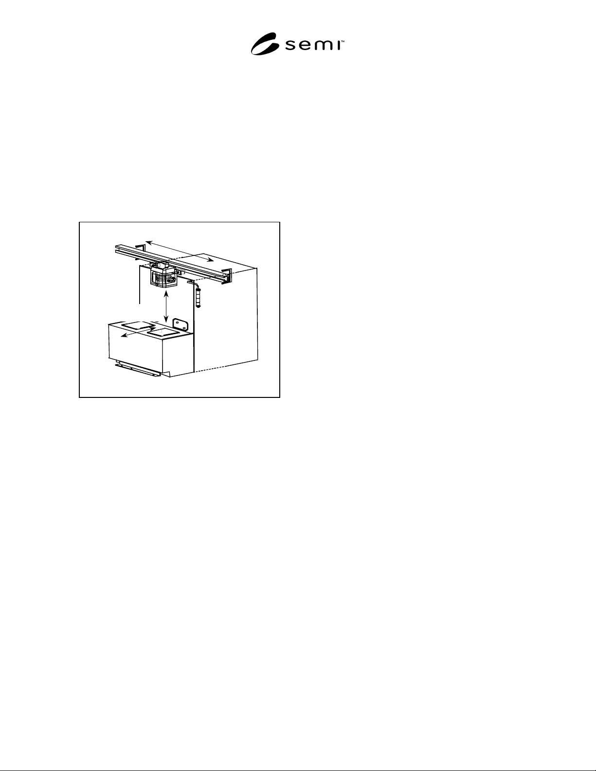
5.19 travel — the automated motion of a vehicle along
a rail or programmed path from one station to another
station. Travel does not include load/unload operation.
See Figure 1.
5.20 unmanned transport vehicle (UTV) — a vehicle
used to automate the movement of production material
within semiconductor factories. There are two types of
UTVs, floor-traveling vehicles and space-traveling
vehicles.
Travel
Station to Station
Load/Unload
Overhead or Floor Vehicle
Figure 1
Delineation of Travel vs. Load/Unload
6 Equipment Evaluation
6.1 Equipment Evaluation for both Floor-Traveling
and Space-Traveling Vehicles — All UTV equipment
should be evaluated against the following referenced
provisions.
6.2 All UTV equipment should be evaluated against
appropriate sections of SEMI S2 for environmental,
safety, and health considerations.
6.2.1 Evaluations to the provisions in the following
sections of SEMI S2 are applicable to declare
conformance to this document.
a) Electrical Design
b) Emergency Shutdown
c) Automated material handlers (This Automated
material handlers section only applies to the
robotics portion of UTV equipment, when
provided.)
d) Hazard Warning Labels
e) Seismic Protection
f) Documents provided to User
6.2.2 At the discretion of the evaluator, additional
provisions in SEMI S2 may be considered for
evaluation based on the functionality of the UTV
equipment.
6.3 All UTV equipment should be evaluated against
SEMI S8 for ergonomic considerations.
6.4 All UTV equipment should be evaluated against
the applicable Electro Magnetic Compatibility (EMC)
regulations of the proposed installation site.
6.5 In addition to the provisions referenced in Section
6.1, UTV equipment should also be evaluated to the
provisions contained in the following sections of this
document.
7 Clearances and Interfaces
7.1 Body Shape of both Floor-Traveling and Space-
Traveling Vehicles — The body of a UTV should be
free of any dangerous parts such as sharp edges and
protrusions. The UTV body surface should have a
smooth finish.
7.2 Minimum Clearance for Floor-Traveling Vehicles
— Where passageways are used for emergency egress,
they should be provided on at least one side of the
UTV. International, national or local codes,
regulations, and laws should be used to determine
passageway width.
7.3 Minimum Clearance for Space-Traveling Vehicles
— The lowest part of the space-traveling vehicle,
including the load, should maintain a minimum
clearance of 2135 mm (7 feet) above the walking floor.
NOTE 3: Some end user customers may request a higher
minimum clearance, or a minimum clearance between the
space-traveling vehicle and the top of other equipment, to
accommodate clearances specified by SEMI E15.1.
7.4 Interfaces with Building Structures for both Floor-
Traveling and Space-Traveling Vehicles
UTV
suppliers should provide for optional vehicle interfaces
with building structures like doors, elevators, and walls.
7.4.1 If UTVs are required to operate in conjunction
with building structures, such as automatic doors or
elevators, UTVs should be capable of communicating
with the facility to assure safe door opening/closing.
7.4.2 If it is necessary for a UTV to travel through a
building firewall, the firewall pass through should be
specified and/or designed to maintain the fire rating of
the wall in the event of a fire.

SEMI S17-0701 © SEMI 2001 4
8 Emergency Shutdown
8.1 Emergency Shutdown for both Space-Traveling
and Floor-Traveling Vehicles — In addition to the
emergency shutdown provisions of SEMI S2, UTV
equipment should also conform to the following
provisions.
8.1.1 The UTV should be equipped with an emergency
off (EMO) circuit that, when activated, immediately
stops the operation and motion of the UTV, including
both travel and load/unload operation. The EMO circuit
should be activated whenever the following actions
occurs:
a) An EMO button on the UTV is pressed.
b) An EMO at a fixed floor location is pressed.
NOTE 4: See Section 9.2 for handheld remote control.
8.1.2 Once an EMO circuit has been activated, the
UTV should not move under its own power until the
cause of the emergency condition has been resolved and
the system has been reset by a human operation. The
system should not reset or restart automatically.
8.2 Position of EMO Buttons on Floor-Traveling
Vehicles — Structure-mounted EMO buttons should be
located for easy accessibility by factory personnel.
8.2.1 Vehicle-mounted EMO Buttons should be
accessible and visible from all sides of the vehicle,
typically on the four-corners of a floor-traveling
vehicle.
8.3 Position of EMO Buttons for Space-Traveling
Vehicle Systems
EMO buttons should be located for
easy accessibility by factory personnel, for example:
• Near control panels or operator terminals including
handheld vehicle remote controls.
• Near process equipment load ports or stations.
• On walls or other fixed locations in the factory area
where space-traveling vehicles operate.
NOTE 5: Some end user customers may request EMO buttons
included on the space-traveling vehicle.
8.3.1 Since space-traveling vehicle EMO buttons are
typically remote from the vehicles, space-traveling
systems should provide a method of determining the
location of the activated EMO button. This will ensure
that the emergency condition can be identified and
resolved prior to resetting the system per Section 8.1.2.
9 Manual Operation
9.1 Manual Movement of both Space Traveling and
Floor-Traveling Vehicles — When the EMO is
activated, the UTV should be capable of brake release
to allow for release of a potentially trapped person.
9.1.1 The UTV should be equipped with a manual
movement function that permits a human operator to
maneuver the vehicle in the event of a problem. In the
event of a problem, manual movement of all vehicle
functions including travel and load/unload
should be
allowed.
9.2 Manual/Remote Operation of both Space-
Traveling and Floor-Traveling Vehicles — Except for
EMO and E-Stop, any control of a vehicle outside of
automated operation should be exclusive. Other
devices should not override vehicle control or cause
movement of more than one vehicle at a time.
EXCEPTION:Those controls that do not cause motion.
9.2.1 Manual control of a vehicle motion that could
present a hazard if control is lost should be controlled
with an enabling type switch, such that movement is
enabled only when a switch is continuously held
(pressed) by an operator.
9.2.1.1 Handheld remote controls should have an E-
Stop or EMO function to allow operators to stop
movement that could cause risk to themselves or others.
If remote control is wireless, this function should not be
marked or labeled as an EMO.
9.2.1.2 During handheld remote control operation, the
UTV should stop any vehicle motion that could create a
hazard if power or the communication signal is lost.
10 Vehicle Travel
10.1 Collision Avoidance for both Space-Traveling
and Floor-Traveling Vehicles — UTVs should provide
for protection of persons in the same traveling space
from injury. Damage to property or equipment from
traveling vehicles should also be prevented.
10.1.1 The UTV system supplier should provide
documentation specifying safe practices for working
within traveling space of the UTVs, to include
documented administrative procedures necessary to
work safely while performing maintenance on or near
operating UTV systems.
10.1.2 UTVs should be equipped with non-contact
approach sensing system so those vehicles do not
inadvertently contact people or other obstacles during
the traveling motion of the UTV. Non-contact
approach sensing systems should consist of either
electromechanical (preferred) or solid-state devices and
components and be designed to be fault-tolerant.
10.1.2.1 If an overhead vehicle is provided with a
fault-tolerant contact sensing system (such as a bumper
switch), as primary safety protection for people, the

SEMI S17-0701 © SEMI 20015
circuitry of the secondary non-contact system is not
limited to electromechanical or solid state devices and
components.
10.1.2.2 Where solid-state devices and components
are used in an approach sensing system circuit, the
system and relevant parts of the system should be
evaluated for suitability for use. Abnormal conditions
such as overvoltage, undervoltage, power supply
interruption, transient overvoltage, ramp voltage,
electromagnetic susceptibility, electrostatic discharge,
thermal cycling, humidity, dust, vibration, and jarring
should be considered.
EXCEPTION: When the severity of a reasonably foreseeable
mishap is deemed to be Minor per SEMI S10, a software
based control may be considered suitable.
10.1.2.3 Upon request by the user customer, suppliers
should provide a test piece or set of test pieces
(appropriate to the sensor device provided) along with
procedures for testing and calibration.
10.1.3 When a UTV detects a vehicle or obstacle, the
UTV should decelerate and stop automatically before it
touches that vehicle or obstacle. If the non-contact
approach sensing device should be disabled (for
example because the UTV is negotiating a sharp turn),
the UTV should decelerate and issue a warning (see
Hazard Alarms and Displays section of this document)
to indicate that the sensing device has been disabled.
10.1.4 In an area where multiple UTVs are operating,
the capability to prevent the collision of one vehicle
with another should be provided and to satisfy Section
10.1.3, should consider the following conditions:
a) The distance between a given vehicle and the
vehicle that follows it.
b) The timing at which one stream of vehicles merges
with another.
c) The timing at which a vehicle branches out from a
stream of vehicles to pass another vehicle moving
toward it.
d) The distance that separates two vehicles when they
pass each other.
10.2 Collision Detection for Floor-Traveling Vehicles
— In addition to Section 10.1, floor-traveling vehicles
should also be equipped with a contact sensing device
(such as a bumper switch) capable of detecting collision
in the direction in which motion can create a hazard.
10.2.1 The bumpers should have a shape and structure
that does not pose a risk to personnel or to objects
around the floor-traveling vehicle.
10.2.2 The bumpers should be equal to or larger than
the width of the floor-traveling vehicle body, as
measured perpendicular to the direction of its traveling
motion.
10.2.3 The maximum allowable distance between a
bumper and the floor is 15 mm (0.6 inch).
EXCEPTION: If this provision cannot be maintained, (such
as when the floor-traveling vehicle enters an elevator, or
changes in floor height) the distance should be explicitly
stated in the operation manuals (and the specifications) as an
alert or warning notice to appropriate personnel.
10.2.4 If an obstacle contacts a bumper, the floor-
traveling vehicle should be able to stop within the
bumper stroke, irrespective of the speed at which the
vehicle is traveling. If this provision cannot be met for
technical reasons, the floor-traveling vehicle supplier
should clearly indicate the maximum speed at which the
vehicle can stop within the bumper stroke.
10.2.5 There should not be any device that disables the
functionality of the bumper switch or sensor on floor-
traveling vehicles.
10.2.6 If a bumper switch or sensor has been activated
by contact, a floor-traveling vehicle should not restart
until the system has been reset by a human operation.
NOTE 6: Since space-traveling vehicles travel in dedicated
space above the heads of factory personnel, criteria for space-
traveling vehicle bumpers are not included.
10.3 Protective Zones for Space-Traveling Vehicles —
Written administrative procedures for creating a
protective zone around personnel, required to work
overhead in the path of space-traveling vehicles, should
be included in documentation provided by the UTV
system supplier.
NOTE 7: Implementation of these administrative procedures
is the responsibility of the end user customer.
10.4 Travel Speed of Floor-Traveling Vehicles —
Floor-traveling vehicles, intended for use in areas
where there are both operating vehicles and personnel
present, should be equipped with a variable speed-
setting mechanism.
10.4.1 The variable speed settings designed for use in
areas with both operating vehicles and personnel should
not exceed 60 meters/minute (196 feet/minute). Any
variable speed settings exceeding 60 meters/minute
(196 feet/minute) should be reserved for use in
dedicated and unmanned areas for which personnel
safety can be assured.
10.4.2 The variable speed setting mechanism of a
floor-traveling vehicle should be designed so that only
authorized personnel, following access control
procedures, can change the vehicle’s speed setting.
NOTE 8: Criteria for traveling speeds of space-traveling
vehicles are not included in this sub-section.