semi合集-English.pdf - 第4318页
SEMI F85-0304 © SEMI 2004 4 RELATED INFORMATION 1 EXAMPLES OF SEAL DESIGNS FOR 1.125 INCH TYPE SURFACE MOUNT COMPONENTS NOTICE: This relate d inform ation is not an official pa rt of SEMI F 85 and was derived f rom the w…

SEMI F85-0304 © SEMI 2004 3
7 Related Documents
7.1 ISO Standards
2
ISO 406 — Technical Drawings - Tolerancing of
Linear and Angular Dimensions
ISO 1101 — Technical Drawings - Geometrical
Tolerancing - Tolerancing of Form, Orientation,
Location, and Run-Out - Generalities, Definitions,
Symbols, and Indications on Drawings.
ISO 1660 — Technical Drawings - Dimensioning and
Tolerancing of Profiles
ISO 2692 — Technical Drawings - Geometrical
Tolerancing - Maximum Material Principle
ISO 6507 — Metallic Materials - Vickers Hardness
Test
ISO 8015 — Technical Drawings - Fundamental
Tolerancing Principles
NOTICE: SEMI makes no warranties or
representations as to the suitability of the standards set
forth herein for any particular application. The
determination of the suitability of the standard is solely
the responsibility of the user. Users are cautioned to
refer to manufacturer' s instructions, product labels,
product data sheets, and other relevant literature,
respecting any materials or equipment mentioned
herein. These standards are subject to change without
notice.
By publication of this standard, Semiconductor
Equipment and Materials International (SEMI) takes no
position respecting the validity of any patent rights or
copyrights asserted in connection with any items
mentioned in this standard. Users of this standard are
expressly advised that determination of any such patent
rights or copyrights, and the risk of infringement of
such rights are entirely their own responsibility.
2 ISO Central Secretariat, 1, rue de Varembé, Case postale 56, CH-
1211 Genevè 20, Switzerland. http://www.iso.ch
SEMI F85-0304 © SEMI 2004 4
RELATED INFORMATION 1
EXAMPLES OF SEAL DESIGNS FOR 1.125 INCH TYPE SURFACE
MOUNT COMPONENTS
NOTICE: This related information is not an official part of SEMI F85 and was derived from the work of the
originating task force. This related information was approved for publication by full ballot procedures.
Determination of the suitability of the material is solely the responsibility of the user.
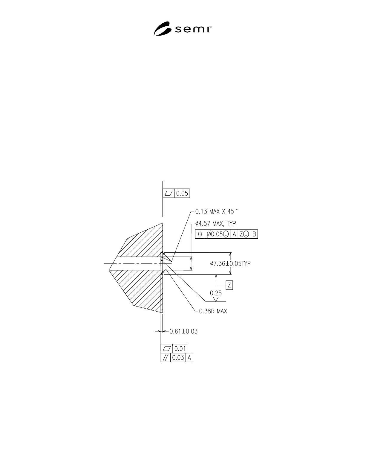
R1-1 Design Example 1
R1-1.1 Seal Design — See Figure R1-1.
R1-1.2 Surface Hardness — The sealing surface (the bottom of the counterbore) has a minimum hardness of 170
Vickers. The hardness may be tested per ISO 6507.
R1-1.3 Surface Roughness — The sealing surface (the bottom of the counterbore) has a surface roughness of 0.25
micrometers Ra max. The surface roughness may be tested per SEMI F37-0299.
R1-1.4 Surface Scratches — The sealing surface (the bottom of the counterbore) is without any lateral scratches
which are visible to non-magnified normal vision.
Figure R1-1
Design Example 1
SEMI F85-0304 © SEMI 2004 5
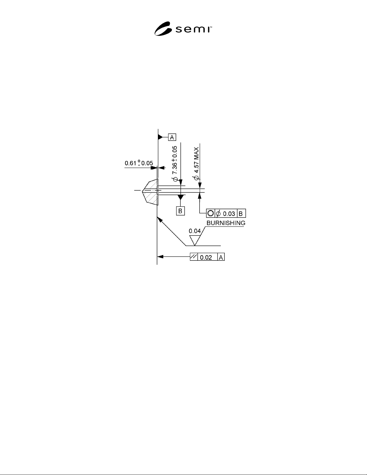
R1-2 Design Example 2
R1-2.1 Seal Design — See Figure R1-2.
R1-2.2 Surface Hardness — The sealing surface (the bottom of the counterbore) has a minimum hardness of 300
Vickers. The hardness may be tested per ISO 6507.
R1-2.3 Surface Roughness — The sealing surface (the bottom of the counterbore) has a surface roughness of 0.04
micrometers Ra max. The surface roughness may be tested per SEMI F37-0299.
R1-2.4 Surface Scratches — The sealing surface (the bottom of the counterbore) is without any lateral scratches
which are visible to non-magnified normal vision.
Figure R1-2
Design Example 2