semi合集-English.pdf - 第1617页
SEMI E38-1296 © SEMI 1995 , 1996 6 Figure 2 Cluster Tool M odule Co mm unicatio ns Standar ds This stan dard describes the clus ter tool model on which the commun ications are bas ed. It then defines the application of e…
SEMI E38-1296 © SEMI 1995, 19965
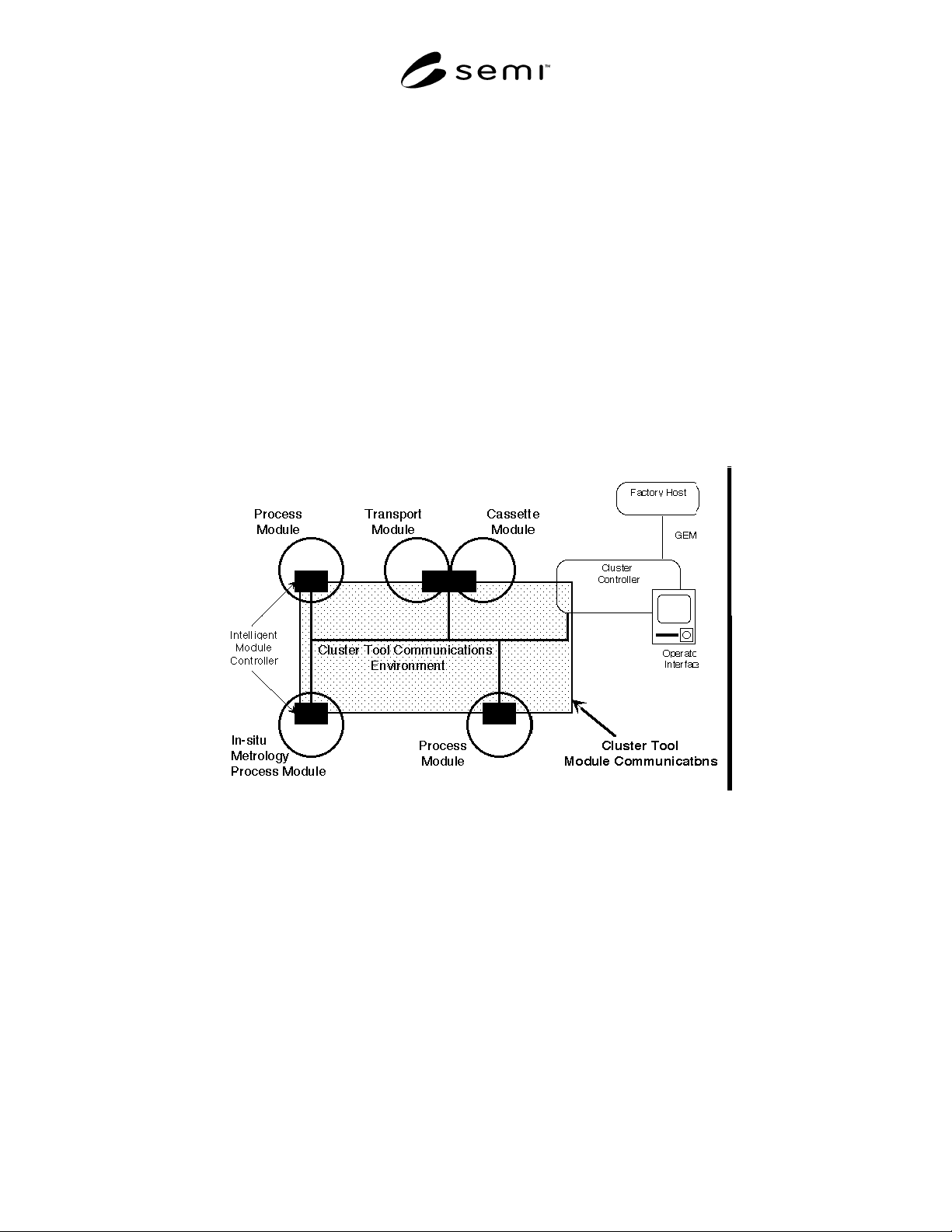
From a mechanical viewpoint, Cluster Tool Module Interface standards-compliant equipment has a physical
structure where process modules and cassette modules are attached in a standardized way to some form of transport
module, a robotic material handler operating in an isolated environment. Cassette modules provide the input and
output of material for the cluster tool, usually in cassettes.
This communications standard enables the distributed control of these cluster tools, and of other cluster tools and
multi-resource equipment which can be decomposed into process, transport, and cassette modules, whether
environmentally isolated or not. A basic assumption is made that the primary human-machine interfaces are not
located at the individual modules.
Communication and control services are specified among service-users and service-providers within a cluster tool.
The service-providers are the controlled processing, transfer, intratool port, and intertool port resources in the
appropriate modules. The service-users are the application entities responsible for supervisory control and data
acquisition within the cluster tool.
The services are fully defined in terms of the service-providers, and as such, do not dictate the architecture of the
service-user(s). An example of cluster tool control architecture is shown in Figure 1, where the service-user is a
single cluster controller platform providing internal scheduling, human-machine interface, and standardized
communications interface to the factory.
Figure 1
Example Cluster Control Architecture
The communication services include primary control services for material processing in process modules
(processing management) and material movement within the cluster tool and material input/output with the factory
(material movement management). The cluster controller, which is responsible for supervisory control within the
cluster tool, is the service-user of these primary control services. The form of the cluster controller is not dictated. It
may be a single platform, distributed, or incorporated with one or more modules.
Support services are also specified to enable resolution of exception conditions, recipe handling, event reporting and
data access. The decision authority, which is responsible for making error recovery decisions, is the service-user for
exception management. Appropriate agents are the designated service-users for the recipe management and event
reporting support services. All service-users access data using the Object Services.
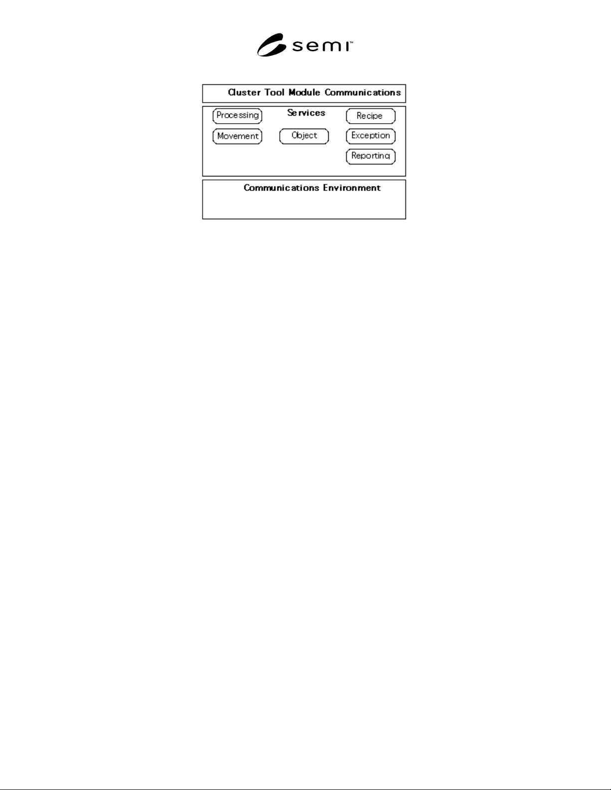
The communications services are defined independently of protocol in order to allow future standardization of
alternative protocols without invalidating the services. Figure 2 shows the full communications stack needed for
compliance, where the services are mapped to the communications environment, which is defined in supplementary
standards.
SEMI E38-1296 © SEMI 1995, 1996 6
Figure 2
Cluster Tool Module Communications Standards
This standard describes the cluster tool model on which
the communications are based. It then defines the
application of each of the services required within a
cluster tool. This includes limitations imposed by the
cluster architecture as well as clear a statement of the
fundamental requirements in order to minimize the
implementation effort. Connection establishment and
maintenance are defined together with the requirements
of the communications environment. Communications
environment is described in a subsection in order to
allow additional options to be standardized in the
future. The application notes include factory integration
issues and an example scenario of standard
communications for the lifecycle of a single material in
a cluster tool.
6.1 Compliance — Cluster tool module
communications compliance between entities in a
cluster tool requires that all applicable exposed
interfaces conform to the standards specified in this
document.
The standardized interfaces are:
• Process module to Service-user (cluster controller)
• Transport module to Service-user (cluster
controller)
• Cassette module to Service-user (cluster controller)
• Transport module to Cassette module
• Transport module to Process module
The exposed interfaces are those which result from a
particular partition of the control entities in a cluster
tool which are from independent suppliers. Three
examples follow:
1. All modules independent, single cluster controller
platform: Interfaces are required between the
cluster controller and each module, and between
the transport module and each process and each
cassette module.
2. Material handler, process modules independent,
single cluster controller platform: Interfaces are
required between the cluster controller and each
process module, between the cluster controller and
each logical module in the material handler
(transport and cassette modules), and between the
material handler and each process module.
3. One independent process module integrating to a
cluster tool control system: Interfaces are required
between the cluster tool control system and the
process module supporting the process module to
cluster controller communications, and the process
module to transport module communications.
For fundamental compliance, each exposed interface
shall support the fundamental requirements of each of
the service groups required by the entities
communicating. The required service groups for each
interface are detailed in Section 8.6, and the required
services for each service group are detailed in Sections
8.1 to 8.6.
7 Concepts
The Cluster Tool architecture and requirements are
modeled in order to extract only the entities necessary
for robust automated control and monitoring
communications within a cluster tool.
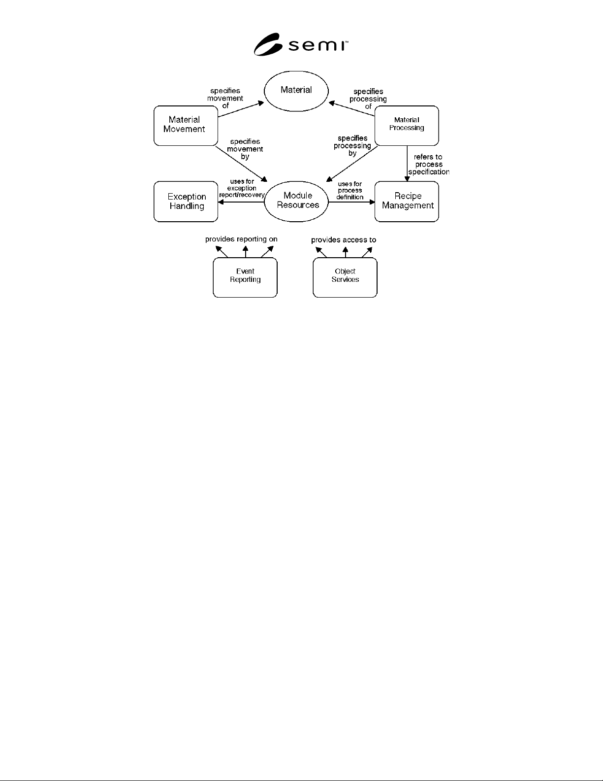
Figure 3 illustrates the major module domains and the
primary relationships between them. Module resources
and material domains are represented differently to
others because they embody the physical entities acting
and being acted upon respectively.
SEMI E38-1296 © SEMI 1995, 19967
Figure 3
Cluster Tool Module Illustration
The domains illustrated are as follows:
Material — The material, or carrier of material, which
is being received and processed in the cluster tool.
Material Processing — Specifies the required
application of processing to material as defined by the
assigned recipe, adding value to the material.
Material Movement — Includes exchange of material
with the factory and material movement within the
cluster, to get the material to the correct processing
resource at the right time.
Module Resources — Perform and coordinate the
processing and material movement activities.
Recipe Management — Provides the services to transfer
recipes to be loaded as required for material processing,
and manages recipe change control.
Exception Handling — Provides for interactive
handling of exception conditions, including reporting
and error recovery.
Event Reporting — Enables flexible event-based
reporting of variable data as required by service-users.
Object Services — Provide services to obtain and
modify standard object attribute data.
Each partition is presented in a subsection below with
detailed information models.
The concepts are presented in this section using two
types of formal models: OMT object information
models describing entities and relationships, and Harel
state models describing the behavioral characteristics of
the cluster tool. The graphical representations of these
models are described in Conventions, Section 5.
The events and actions which result from objects
dynamically interacting form the basis for the
communication requirements embodied in the
standards. It is this mapping that specifies the
communication services messages to be used.
The major requirement of the cluster tool control
system is that it provide robust supervisory control with
minimal overhead. Within a cluster tool there is a
significant amount of parallel processing. In addition to
concurrent processing in multiple independent process
modules, each material processing requires the use of
recipe management (to get the correct recipe with the
correct material) and the use of material movement (to
get the correct material to the correct processing
resource at the right time).
The cluster controller maintains the overall mission of
the system. Sub-missions are defined for, and
responsibility given to, particular available module
resources for execution. Once this responsibility is
given, that module resource is fully in control,
including direct communication with resources of other
modules as required to attain the objective.
7.1 Object Information Models — The cluster tool
objects relevant to distributed control in a number of
models, each emphasizing a particular aspect of the
system as partitioned (see Figure 4).