semi合集-English.pdf - 第5917页
SEMI P39-0304 E2 © SEMI 2004 20 24.7 EXCEPTION HANDL ING — Use of a reference-number for which there is no corresponding TEXTSTRING record within the same OASIS file should be treated as a fatal error. Implicit use of mo…
SEMI P39-0304
E2
© SEMI 2004 19
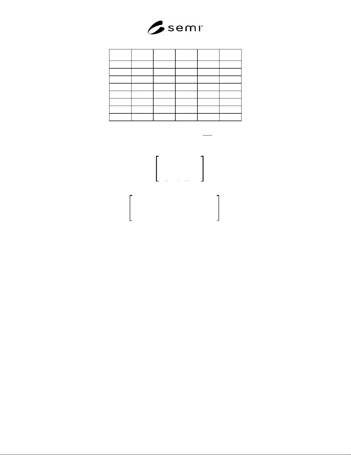
Table 14 Standard Placement Values
F angle X00 X01 X10 X11
0 0° +1 0 0 +1
1 0° +1 0 0 1
0 90° 0 +1 1 0
1 90° 0 +1 +1 0
0 180° 1 0 0 1
1 180° 1 0 0 +1
0 270° 0 1 +1 0
1 270° 0 1 1 0
23.2 When repetition is present, the above transform is that of the first
element of the repetition. In general, the
transform of any element E of the repetition is computed by right-multiplying the transform of the first element by
the matrix:
1
0
x-offset
0
1
y-offset
0
0
1
S =
to yield:
X00
X10
(X20 +
x-offset
)
X01
X11
(X21 +
y-offset
)
0
0
1
(Refer to Section 7.6.3 and subsequent paragraphs beginning on page 7 for a discussion of how x-offset and y-offset
are determined for the various repetition types.)
24 TEXT Record
24.1 A TEXT record represents a text element, consisting of an (x,y) coordinate point and an annotation string. It
has the following format:
‘19’ text-info-byte [ reference-number | text-string] [ textlayer-number ] [ texttype-number ]
[ x ] [ y ] [ repetition ]
24.2 The text-info-byte contains the bit pattern ‘0CNXYRTL’.
24.3 When C = 1, the text reference is explicit, in which case N = 1 means that reference-number (an unsigned-
integer) is present, and refers to a TEXTSTRING record where the text string is stored; N = 0 means that text-
string (an a-string) is present and stores the text string locally. When C = 0, N is ignored, and the value of modal
variable text-string is used instead.
24.4 x and y are signed-integer coordinates representing either the absolute or the relative (x,y) location of the text
element. X is 1 if x is present, and Y is 1 if y is present. When either x or y is unspecified, the value of modal
variable text-x or text-y, respectively, is used instead. Refer to Section 21 on page 17 for a discussion of how
absolute and relative modes affect the interpretation of x and y.
24.5 R is 1 if repetition
is present. L is 1 if textlayer-number is present. T is 1 if texttype-number is present.
Both textlayer-number and texttype-number are unsigned-integers. When textlayer-number and/or texttype-
number are unspecified, they assume the value of modal variables textlayer and texttype, respectively.
24.6 Each successive TEXT record updates all text-related modal variables.
SEMI P39-0304
E2
© SEMI 2004 20
24.7 EXCEPTION HANDLING — Use of a reference-number for which there is no corresponding
TEXTSTRING record within the same OASIS file should be treated as a fatal error. Implicit use of modal variables
textlayer or texttype when they are in the undefined state should be treated as a fatal error.
25 RECTANGLE Record
25.1 A RECTANGLE record represents a rectangular figure whose edges are parallel to the x- and y-axes. It has
the following format:
‘20’ rectangle-info-byte [ layer-number ] [ datatype-number ] [ width ] [ height ] [ x ] [ y ] [ repetition ]
25.2 The rectangle-info-byte contains the bit pattern ‘SWHXYRDL’.
25.3 R is 1 if repetition is present. L is 1 if layer-number is present. D is 1 if datatype-number is present. Both
layer-number and datatype-number are unsigned-integers. When layer-number and/or datatype-number are
unspecified, they assume the value of modal variables layer and datatype, respectively. W is 1 if width is present.
H is 1 if height is present. Both width and height are unsigned-integers. When width and/or height are
unspecified, they assume the value of modal variables geometry-w and geometry-h, respectively.
25.4 S is 1 if the rectangle is a square. In this case, H must be 0, and width, if present, is used for both dimensions
of the rectangle. When width is unspecified, the value of modal variable geometry-w is used instead.
25.5 x and y
are signed-integer coordinates representing either the absolute or the relative (x,y) location of the
lower-left corner of the rectangle. X is 1 if x is present, and Y is 1 if y is present. When either x or y is unspecified,
the value of modal variable geometry-x or geometry-y, respectively, is used instead. Refer to Section 21 on page 17
for a discussion of how absolute and relative modes affect the interpretation of x and y.
25.6 Each successive RECTANGLE record updates all rectangle-related modal variables. (When S = 1, both
geometry-w and geometry-h are set to the rectangle’s width.)
25.7 EXCEPTION HANDLING
— Implicit use of modal variables geometry-w, geometry-h, layer, or datatype
when they are in the undefined state should be treated as a fatal error. When S = 1, H = 1 should be treated as a fatal
error. The interpretation of zero-area RECTANGLEs is application-dependent.
26 POLYGON Record
26.1 A POLYGON record represents an arbitrary polygon figure. It has the following format:
‘21’ polygon-info-byte [ layer-number ] [ datatype-number ] [ point-list ] [ x ] [ y ] [ repetition ]
26.2 The polygon-info-byte contains the bit pattern ‘00PXYRDL’.
26.3 x and y are signed-integer coordinates representing either the absolute or the relative (x,y) location of the
initial vertex of the polygon. X is 1 if x is present, and Y is 1 if y is present. When either x or y is unspecified, the
value of modal variable geometry-x or geometry-y, respectively, is used instead. Refer to Section 21 on page 17 for a
discussion of how absolute and relative modes affect the interpretation of x and y.
26.4 R is 1 if repetition is present. L is 1 if layer-number is present. D is 1 if datatype-number is present. Both
layer-number and datatype-number are unsigned-integers. When layer-number and/or datatype-number are
unspecified, they assume the value of modal variables layer and datatype, respectively.
26.5 P
is 1 if point-list is present. Otherwise, the value of modal variable polygon-point-list is used. The format of
point-lists is defined in Section 7.7 on page 9.
26.6 Each successive POLYGON record updates all polygon-related modal variables.
26.7 EXCEPTION HANDLING
— Polygons with fewer than three vertices should be treated as fatal errors. Implicit
use of modal variables polygon-point-list, layer, or datatype when they are in the undefined state should be treated
as a fatal error. The interpretation of self-intersecting polygons, reentrant polygons, and polygons with zero-area
regions is application-dependent.

SEMI P39-0304
E2
© SEMI 2004 21
27 PATH Record
27.1 A PATH record represents an arbitrary path figure, which may be thought of as a polyline with finite width. It
has the following format:
‘22’ path-info-byte [ layer-number ] [ datatype-number ] [ half-width ]
[ extension-scheme [ start-extension] [ end-extension ] ] [ point-list ] [ x ] [ y ] [ repetition ]
27.2 The path-info-byte contains the bit pattern ‘EWPXYRDL’.
27.3 x and y are signed-integer coordinates representing either the absolute or the relative (x,y) location of the
initial vertex of the path centerline. X is 1 if x is present, and Y is 1 if y is present. When either x or y is unspecified,
the value of modal variable geometry-x or geometry-y, respectively, is used instead. Refer to Section 21 on page 17
for a discussion of how absolute and relative modes affect the interpretation of x and y.
27.4 R is 1 if repetition is present. L is 1 if layer-number is present. D is 1 if datatype-number is present. Both
layer-number and datatype-number are unsigned-integers. When layer-number and/or datatype-number are
unspecified, they assume the value of modal variables layer and datatype, respectively.
27.5 P is 1 if point-list is present. Otherwise, the value of modal variable path-point-list is used. The format of
point-lists is defined in Section 7.7 on page 9.
27.6 W
is 1 if half-width (an unsigned-integer) is present; if absent, the half-width value assumes the value of
modal variable path-halfwidth. The path is formed by expanding the centerline (represented by line segments
connecting the points) by the half-width value to each side.
27.7 E is 1 if extension-scheme is present. Otherwise, extension-scheme, start-extension, and end-extension are
absent, and the values of modal variables path-start-extension, and path-end-extension are used instead.
27.8 When present, extension-scheme (an unsigned-integer) contains bit pattern ‘0000SSEE’. The SS bits govern
the path starting extension, and the EE bits govern the path ending extension. Both start-extension (present only
when SS = ‘11’) and end-extension (present only when EE = ‘11’) are signed-integers, as in GDSII Stream, with
positive values causing the path to extend beyond its starting and/or ending vertices, and negative values causing the
path to retract from its starting and/or ending vertices.
Table 15 Path Extension Schemes
SS Bits Description
00 Use path-start-extension modal variable
01 Use flush (zero-length) extension at starting vertex
10 Use path-halfwidth extension at starting vertex
11 Use explicit start-extension at starting vertex
EE Bits
00 Use path-end-extension modal variable
01 Use flush (zero-length) extension at ending vertex
10 Use path-halfwidth extension at ending vertex
11 Use explicit end-extension at ending vertex
27.9 Each successive PATH record updates all path-related modal variables.
27.10 Various types of degenerate paths, where the half-width = 0, the path traces back on itself, an extension is
negative with magnitude greater than its segment length, etc. are not prohibited; their interpretation is application-
dependent. The path expansion scheme used at the path’s interior vertices or “joints” is also application-dependent.
27.11 EXCEPTION HANDLING
— Implicit use of modal variables path-halfwidth, path-point-list, path-start-
extension, path-end-extension, layer, or datatype when they are in the undefined state should be treated as a fatal
error.