semi合集-English.pdf - 第4174页
SEMI F69-0302 © SEMI 2002 2 sy stems to t he equi valen t physical stress of a 4828 kilom eter (3000 mile) m otor freigh t shi pment ov er improv ed or paved hig hway s. Because vibration tables are comm o nly single-ax …

SEMI F69-0302 © SEMI 2002 1
SEMI F69-0302
TEST METHODS FOR TRANSPORT AND SHOCK TESTING OF GAS
DELIVERY SYSTEMS
This test method was technically approved by the Global Facilities Committee and is the direct responsibility
of the North American Facilities Committee. Current edition approved by the North American Regional
Standards Committee on November 27, 2001. Initially available at www.semi.org December 2001; to be
published March 2002.
1 Purpose
1.1 This document provides test methods for qualifying
the mechanical integrity of gas delivery systems
through vibration and shock testing.
2 Scope
2.1 The test methods recommended herein provide for
vibration (transport simulation) and shock testing of gas
delivery systems for semiconductor processing.
2.2 The test methods recommended herein apply to gas
delivery systems not crated or packaged for shipment.
Specifically, the test methods are to be applied to the
assembled and interconnected gas delivery components
and their associated mounting panel (back plane), with
or without a sheet metal enclosure.
2.3 For the purpose of this guideline, transportation
vibration, and its simulation, are expectedly more
severe than in-use vibrational levels. Thus the
transportation simulation test is considered acceptable
to assess mechanical integrity adequate for both
shipment and life-cycle vibrational stress of the gas
delivery systems.
2.4 The intent of the shock test is to provide further
assessment of equipment malfunction that may result
from shocks experienced during unpacking, installation,
or use in the field.
2.5 Successful completion of the tests recommended
herein is a recommended metric of mechanical integrity
for gas delivery systems architecture, design, and
assembly techniques.
2.6 This standard does not purport to address safety
issues, if any, associated with its use. It is the
responsibility of the user of this standard to establish
appropriate safety and health practices and determine
the applicability of regulatory limitations prior to use.
3 Limitations
3.1 This document, as a guide, does not provide
detailed information sufficient for conducting the tests.
It is the responsibility of the user and testing entity to
procure a copy of the referenced test procedures from
the issuing organization(s).
3.2 The test methods recommended herein are intended
to evaluate gas delivery systems architectures, design
principles, and assembly methodologies, not individual
production gas delivery systems.
3.3 The functional components of gas delivery
systems, for example mass flow controllers and
pressure transducers, may be adversely affected by the
forces seen during these tests. Such components may
require recalibration after testing.
4 Referenced Standards
NOTE 1: As listed or revised, all documents cited shall be
the latest publications of adopted standards.
4.1 SEMI Standards
SEMI F1 Specification for Leak Integrity of High-
Purity Gas Piping Systems and Components
4.2 Military Standards
1
MIL-STD-810 Environmental Engineering
Considerations and Laboratory Tests
5 Terminology
5.1 bag leak test A helium leak testing procedure in
which the system undergoing leak test is placed in a
helium-filled plastic bag while connected to a
functional helium leak detector.
5.2 g A unit of force equal to that exerted by gravity
upon a mass in equilibrium on the earth’s surface.
Expressed in Newtons (kg-m/sec.
2
).
5.3 leak tight Having a helium leak rate no greater
than that specified by the customer or end-user.
6 Vibration Testing
NOTE 2: Vibration testing should be performed in its entirety
before continuing to the shock testing.
6.1 In general, conduct vibrational testing according to
MIL-STD-810, Part Two, Laboratory Test Method
514.5, Procedure 1, Category 4, for 3 hours in each axis
(a total of 9 hours). This will subject the gas delivery
1 DODSSP, Building 4 / Section D, 700 Robbins Avenue,
Philadelphia, PA 19111-5094

SEMI F69-0302 © SEMI 2002 2
systems to the equivalent physical stress of a 4828
kilometer (3000 mile) motor freight shipment over
improved or paved highways. Because vibration tables
are commonly single-axis devices, the gas delivery
systems will be subjected to single-axis random
vibrational frequencies in the range of 5—500 Hz,
sequentially, in each of its three axes.
6.2 Prior to initiating the test, examine the gas delivery
systems for physical defects and document the results.
6.3 Prior to initiating the test, thoroughly prepare the
gas delivery systems for testing. This includes, but is
not limited to, insuring all fasteners and sealing
mechanisms are tightened to manufacturers’ or design
specifications.
6.4 The MIL-STD-810 transportation test
recommended herein provides for different acceleration
levels for each of the 3 axes of the device under test.
Because the majority of gas delivery systems are
shipped in a vertical orientation, this convention is
maintained for the purpose of the transportation
simulation tests. Thus the vertical orientation would
have the gas delivery system mounted vertically with
respect to the vibration table top (see Figure 2), the
longitudinal orientation would have the gas delivery
system mounted flat to the vibration table top (see
Figure 1), and the transverse orientation would have the
gas delivery system mounted on its side, against the
vibration table top (see Figure 3). Note that the terms
“vertical,” “longitudinal,” and “transverse,” are
contextual to motor freight transport, and receive
different acceleration levels, within MIL-STD-810. A
simplified and conservative approach to applying MIL-
STD-810 involves applying the highest acceleration
level, associated with the vertical axis, to all three
orientations as illustrated in Figures 1–3.
6.5 Mount the gas delivery system, in any of its
untested axes, securely to the vibration table. See
Figures 1–3.
6.6 Prior to initiating the test at the test site, make
certain that the gas delivery system is leak tight using
inboard test procedures per SEMI F1. A bag leak test
method is recommended in conjunction with this test.
6.7 Initiate and run for 3 hours the vibration test
corresponding to the orientation of the gas delivery
system.
6.8 At the conclusion of the test, examine the gas panel
for physical defects and document the results
6.9 At the conclusion of the test, leak test the gas
delivery system using inboard leak procedures per
SEMI F1. A bag leak test method is recommended in
conjunction with this test. Alternatively, by agreement
with the customer, all leak testing may be withheld until
completion of all shock and vibration testing. This
presumes specific failure mode information is not
required.
6.10 Repeat Sections 6.5 through 6.9 until all 3 axes
are tested.
6.11 The post-test report should include, at minimum,
the following:
(1) Pre-test examination results.
(2) Pre-test leak rates.
(3) Summary and chronology of test events, test
interruptions, and test failures.
(4) All vibration measurement data.
(5) Post-test examination results.
(6) Post-test leak rates.
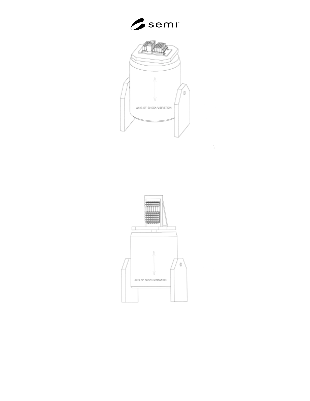
SEMI F69-0302 © SEMI 2002 3
NOTE 1: Plane of gas sticks is parallel to shock/vibe table and transverse to test input.
Figure 1
Horizontal Orientation
NOTE 1: Plane and axes of gas sticks are normal to shock/vibe table and parrallel to test input.
Figure 2
Vertical Orientation