semi合集-English.pdf - 第1987页
SEMI E54.5-0997 © SEMI 1997, 2004 3 h) state diagram i) byte j) nibbl e k) character string 5.2 SDS-Specific Defin itions — In ad dition to the above terms, the following t erms are defined for SDS networks. 5.2.1 action…
SEMI E54.5-0997 © SEMI 1997, 2004 2
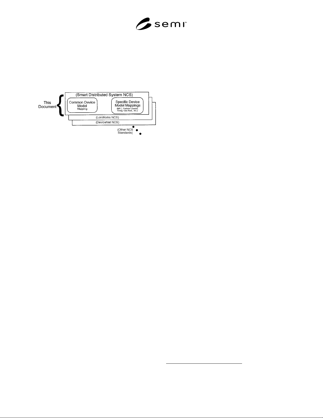
The SDS Network communications standard document
structure is shown in Figure 2. This standard specifies
the mapping of the SAN common device model onto
the SDS-specific network. In addition, the document
will include mappings to specific device models (e.g.,
the mass flow controller). The latter mappings will be
included in this document as the specific device models
are defined.
Figure 2
SDS Network Communications Standard Document
Structure
3 Limitations
3.1 This document specifies a semiconductor
equipment SAN based solely on SDS and is a
companion document to the SDS specification; thus, a
complete specification of this standard necessarily
includes the SDS specifications. There are other
semiconductor equipment SAN communications
options. The specifications for these options are not
included here.
3.2 This standard specifies enhancements that provide
additional capabilities over and above those currently
required by SDS. In order to avoid document
consistency problems, information in the SDS
specification that relates to this standard is not repeated
in this document. This document is limited to
describing enhancements or limitations to the SDS
specification that are imposed by this standard.
3.3 A complete specification of the conformance
testing procedure shall include the SDS protocol
conformance testing specification. Conformance testing
shall also include enhancements and limitations to the
SDS specification required by this standard.
4 Referenced Standards
4.1 SEMI Standards
SEMI E30 — Generic Model for Communications and
Control of SEMI Equipment (GEM)
SEMI E39 — Object Services Standard: Concepts,
Behavior, and Services
SEMI E54.1 — Standard for Sensor/Actuator Network
Common Device Model
4.2 ISO Standards
1
ISO 7498 — Basic Reference Model for Open Systems
Interconnection
ISO 11898 — Road Vehicles — Interchange of Digital
Information — Controller Area Network (CAN) for
High-Speed Communications
4.3 Other Documents
Doc 84-08420-1 (GS 052 103) — SMART
DISTRIBUTED SYSTEM Application Layer Protocol
Specification, Honeywell MICRO SWITCH, February
15, 1995
Doc 84-08421-A (GS 052 104) — SDS Physical Layer
Specification, Honeywell MICRO SWITCH, December
15, 1994
Doc 85-08453-0 (GS 052 107) — SMART
DISTRIBUTED SYSTEM Component Model
Specification, Honeywell MICRO SWITCH, January
29, 1995
Doc GS 052 108 Issue 1 — SMART DISTRIBUTED
SYSTEM Conformance Test Procedure Specification,
Honeywell MICRO SWITCH, January 2, 1995
Controller Area Network Specification: Version 2, R.
Bosch GmbH, + Postfach 50 D-7000, Stuttgart 1,
Germany, 1991
5 Terminology
Terminology that is common to all of the documents in
this SAN series may also be defined in the Sensor
Actuator Network Interoperability Guideline.
Terminology may be reproduced here which is defined
in other SEMI documents.
5.1 Device Component Definitions — This standard is
based on the concepts developed in the Sensor Actuator
Network Common Device Model (SEMI E54)
document and makes use of the following terms defined
in it:
a) device
b) device model
c) object
d) instance
e) attribute
f) behavior
g) service
1
International Organization for Standardization, 1 rue de Varembe,
Case postale 56, CH-1211 Geneva 20, Switzerland

SEMI E54.5-0997 © SEMI 1997, 2004 3
h) state diagram
i) byte
j) nibble
k) character string
5.2 SDS-Specific Definitions — In addition to the
above terms, the following terms are defined for SDS
networks.
5.2.1 actions — operations that a client may request
an Embedded Object to perform. The action typically
modifies the state of the device. Actions are more
powerful than writing to an attribute, in that multiple
input arguments may be provided as part of an action
request. Also, results of the action are typically
returned. Actions, like attributes, have identifiers that
are specific to the type of the object. However, these
identifiers are independent from attribute or event
identifiers. The “request” services specified in SEMI
E54 are implemented as SDS actions.
5.2.2 controller area network (CAN) — a protocol
developed by the Bosch corporation for automotive in-
vehicle networking. The CAN specification specifies
OSI reference model layers 1 and 2, specifically the
physical signaling and media access/data link protocols.
5.2.3 embedded objects — each SDS Logical Device
contains at least one, and at most 32, Embedded
Objects. An SDS Embedded Object is an abstraction
representing an addressable entity “embedded” within a
Logical Device having specific application-related
interface characteristics. These characteristics include a
defined set of attributes, actions, and events that are
specific to the Embedded Object. Combinations of
these Embedded Objects provide a mechanism for
describing an arbitrary sensor/actuator network device.
The behaviors required by SEMI E54 are specified as
part of the definition of attributes, actions, and events.
5.2.4 events — Are used by objects to asynchronously
report the occurrence of events within an Embedded
Object. Event definitions specify the event reports that
a specific Embedded Object type may emit. Events also
have type-specific identifiers. Event definitions include:
a text string defining the semantics of the event, an
event identifier numerical value and textual name, and a
syntax definition. The “notification” services specified
in SEMI E54 are implemented as SDS events.
5.2.5 logical device — It is possible to have one or
more independent Logical Devices within the Physical
Component. This provides the illusion of multiple
devices on the network that actually are implemented
on the same physical hardware. Logical Devices are
distinguished within the Physical Component using
unique SDS bus addresses. The Logical Device defines
a separately addressable entity within a Physical
Component that has an independent interface definition.
5.2.6 physical component — An SDS Physical
Component is an abstraction representing a single
physical package of hardware and software that is
connected to the network. This is equivalent to the
CDM SEMI E54 definition for “device.” The Physical
Component contains one or more Logical Devices.
Table 1 provides a mapping of SEMI E54 definitions to
SDS-specific definitions. Column 2 contains an equal
sign “=” if the definition is used exactly as specified in
SEMI E54. Otherwise, the appropriate SDS-specific
term(s) are identified.
Table 1 Table 1 Mapping of Terms Between SEMI
E54 and SDS
SEMI E54 Term SDS Term
Device =
Device Model Physical Component
Object Embedded Object
Instance =
Attribute =
Behavior Set of Attribute/Action/Event
definitions
Service Actions for Request Services
and Events for Notification
Services
State Diagram =
Byte =
Nibble =
Character String =
6 Communication Protocol High Level
Structure
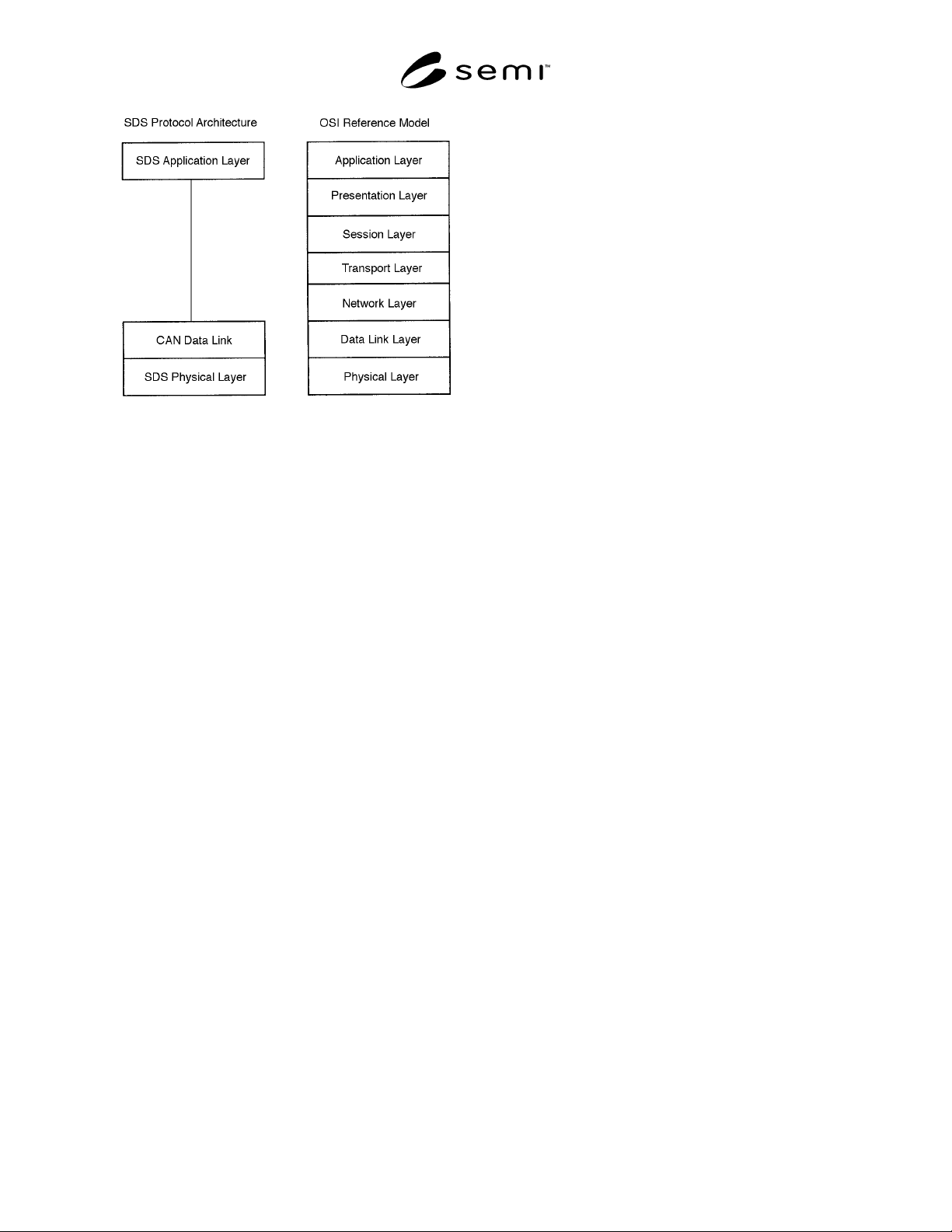
The SDS protocol is based on a three-layer architecture.
These layers constitute a collapsed form of the OSI
seven-layer architecture, mapping into the physical,
datalink, and application layers of the Open Systems
Interconnection Reference Model. The high level
protocol architecture is shown in Figure 3.
Note that Figure 3 represents a conceptual view of the
device architecture. Conforming implementations must
implement the services defined in this specification at
each layer and must appear (from the network) to have
implemented this architecture; however, an internal
modular partitioning is not required. Implementations
may sacrifice modularity in order to achieve high
performance.
SEMI E54.5-0997 © SEMI 1997, 2004 4
Figure 3
Protocol Architecture
SDS uses a three-layer protocol stack consisting of the
physical, datalink, and application layers. The SDS
physical layer uses two twisted pair to deliver power
and data to smart devices at speeds ranging from 125
Kbps to 1 Mbps and distances up to 500 meters. At the
data link layer, the CAN specification defines a carrier
sense multiple access mechanism for media access
control that avoids collisions and sends frames reliably.
The application layer supports a concise set of services
to set and get attributes of objects, to invoke operations
on objects, and to report notifications from objects.
These services are optimized for high performance in
discrete control applications (e.g., 3 byte messages
convey digital I/O state changes). In addition, a set of
pre-defined and extensible component objects flexibly
specifies all network-visible application level device
capabilities.
6.1 Physical Layer — The device shall comply with
the SDS physical layer specifications. These include
physical signaling (levels and baud rates - detailed in
the CAN specification), transceivers, node isolation,
media topology, cable specifications, network
connectors and taps, and power considerations (load
limits, system tolerances, and power supply options).
6.2 Data Link Layer — The device shall comply with
the SDS Data Link Layer Specifications (i.e., Controller
Area Network Specification: Version 2). These include
the media access control mechanism and the logical
link control mechanism. Frame formats, interframe
spacing, and error signaling shall comply with the CAN
specifications. CAN frame identifiers shall be 11 bits in
length.
6.3 Network Layer — There is no distinct network
layer. A future extension of the SDS SEMI SAN
protocol will support inter network messaging.
6.4 Transport Layer — There is no distinct transport
layer. Specific functionality of this layer is
implemented in the Application Layer. Functions
include: segmentation and reassembly for large
message delivery.
6.5 Session Layer — There is no distinct session layer.
6.6 Presentation Layer — There is no distinct
presentation layer. Data types are specified as part of
the SDS object definitions.
6.7 Application Layer — The device shall comply with
the SDS application layer specification. This includes
application object to application object communication
mechanisms.
6.7.1 Object Models — The SDS protocol provides an
object-oriented specification for defining and
addressing objects, including their attributes, actions,
and events. The device shall comply with the object
model specifications provided in the SDS Component
Model Specification. In addition, the device shall
comply with the object specifications defined in Section
7 of this document.
6.8 Network Management — The device shall comply
with the SDS system and network management
specifications.
7 Required Object Types
The Common Device Model specification identifies the
objects that must be supported in SEMI SAN-compliant
devices. These objects are specified in Table 1 of SEMI
E54 and include the following:
a) Device Manager (DM)
b) Sensor/Actuator/Controller (SAC)
c) Sensor (S
i
)
d) Actuator (A
i
)
e) Controller (C
i
).
As specified in SEMI E54, a conforming device must
support the DM, the SAC, and one or more of the
remaining object types.
This section specifies the implementation of these
required and optional objects in the SDS object model.
SDS object types are defined for the DM and SAC
objects. Sensor, actuator, or controller objects may be
implemented using existing standard SDS object types,
or new types may be specified, depending on the
specific device model needs.