semi合集-English.pdf - 第1474页
SEMI E30.5-0302 © SEMI 2001, 2002 2 5.1.5 factory automation cont roller, n . — a computer system that prov ides integration of factory shop control and busi ness s ystems with semi cond uctor eq uipme nt. 5.1.6 feature,…

SEMI E30.5-0302 © SEMI 2001, 20021
SEMI E30.5-0302
SPECIFICATION FOR METROLOGY SPECIFIC EQUIPMENT MODEL
This specification was technically approved by the Global Information and Control Committee and is the
direct responsibility of the North American Global Information and Control Committee. Current edition
approved by the North American Information and Control Committee on October 14 and November 27,
2001. Initially available at www.semi.org December 2001; to be published March 2002. Originally
published July 2001.
The complete specification for this product includes all
general requirements of SEMI E30.
1 Purpose
1.1 This document establishes a Specific Equipment
Model (SEM) for Metrology equipment (MSEM). The
MSEM consists of equipment characteristics and
behaviors that are applicable to this class of equipment
and are required to be implemented in addition to the
SEMI E30 fundamental requirements and additional
capabilities.
2 Scope
2.1 The scope of this document is limited to defining
the behavior of Metrology equipment as perceived by a
SEMI Equipment Communications Standard II (SECS
II/SEMI E5) host that complies with the SEMI E30
model. It defines the view of the equipment through the
SECS II link. It does not define the internal operation of
the equipment. It includes a specific processing state
model as the basis for all equipment behavior of this
class.
2.2 This document assumes that the SEMI E30
fundamental requirements and all additional capabilities
except those noted in SEMI E30 Capabilities Section in
this document have been implemented on the MSEM
equipment. This document expands the SEMI E30
Standard requirements and capabilities in the areas of
the processing state model, collection events, Process
Program management, remote commands, data item
variables, and coordinate systems.
2.3 This standard does not purport to address safety
issues, if any, associated with its use. It is the
responsibility of the users of this standard to establish
appropriate safety and health practices and determine
the applicability of regulatory limitations prior to use.
3 Limitations
3.1 The intent of this document is to facilitate the
integration of Metrology equipment into an automated
semiconductor factory. This document accomplishes
this by defining an operational model for Metrology
equipment as viewed by a factory automation
controller. This definition provides a standard host
interface and equipment operational behavior. This
document applies specifically to Metrology equipment
as used in a semiconductor factory environment. It is
possible that this methodology and techniques may
apply to other industries.
3.2 MSEM job parameters that specify material (e.g.,
carrier ID and substrate ID) and material locations (e.g.,
carrier location ID and carrier slot ID) are intended for
metrology equipment for 200 mm and smaller substrate.
4 Referenced Standards
NOTE 1: As listed or revised, all documents cited shall be the
latest publications of adopted standards.
4.1 SEMI Standards
SEMI E5 SEMI Equipment Communications
Standard II (SECS II)
SEMI M20 — Specification for Establishing a Wafer
Coordinate System
SEMI M21 Assigning Addresses to Rectangular
Elements in a Cartesian Array
SEMI E37.1 High Speed Messaging Service
(HSMS-SS) Single Session
SEMI E58 Automated Reliability and Availability
Standard (ARAMS)
5 Terminology
5.1 Definitions
5.1.1 alignment, n. — a procedure in which a
coordinate system is established on a substrate or a
portion of a substrate.
5.1.2 alignment mark, n. — a feature on a substrate
selectively used for alignment.
5.1.3 alignment site, n. — a point within a feature on a
substrate selectively used for alignment.
5.1.4 cleanup, n. — deselection of the current Process
Program and removal of all material to output locations
and any equipment specific activities required to
transition the equipment into the IDLE state.

SEMI E30.5-0302 © SEMI 2001, 2002 2
5.1.5 factory automation controller, n. — a computer
system that provides integration of factory shop control
and business systems with semiconductor equipment.
5.1.6 feature, n. — a distinctive item in a pattern, or a
physical characteristic of the substrate. (e.g., line,
point, a wafer flat).
5.1.7 field, n. — an exposure repeated in a regular
manner on a substrate.
5.1.8 global alignment, n. — procedure which
establishes a coordinate system for the entire substrate
(see alignment). For silicon wafers, this coordinate
system is defined in MSEM as the SEMI M20
coordinate system.
5.1.9 global pattern alignment, n. — a procedure
which establishes a coordinate reference system relative
to repeating features on an entire substrate. For silicon
wafers, this coordinate system is defined in MSEM as
the M20P coordinate system.
5.1.10 logical port, n. — one or more physical input or
input/output ports that are controlled by the same
execution of a Process Program.
5.1.11 M20P, adj. — a designation used for the global
coordinate system defined within MSEM, that is
established relative to a pattern on a silicon wafer.
5.1.12 material, n. — a piece or pieces of substrate,
one or more substrate, a lot, a batch, or a run.
5.1.13 metrology equipment, n. — any equipment that
collects and reports information on specific
predetermined sites or features on a substrate with
consistent data structure, or reports general information
about the entire substrate.
5.1.14 notch, n. — a cut on the edge of a wafer that is
commonly located with respect to a specific crystal
plane that adheres to the SEMI M1 standard.
5.1.15 pattern, n. — the physical features on a
substrate.
5.1.16 pre-align, n. — any alignment done prior to
placing a substrate on a measurement process location.
5.1.17 registration, n. — positioning error between two
features on different layers of a substrate.
5.1.18 safe state, n. — a state in which the equipment
presents no danger to the product or user. This implies
that safety interlocks are in place such that the
equipment can be serviced without harm to the operator
and that the material being processed has been removed
from the processing station into an accessible location.
5.1.19 secondary alignment, n. — a procedure which
improves the accuracy of the coordinate system
mapping on a substrate in a limited area of the
substrate.
5.1.20 site, n. — a single point on a substrate used for
alignment, or the center of an area of the substrate
within which measurements are made.
5.2 Abbreviations and Acronyms
5.2.1 GEM, n. — Generic Equipment Model
5.2.2 SEM, n. — Specific Equipment Model
5.2.3 SEM, n. — Scanning Electron Microscope
5.2.4 TCP/IP, n. — Transmision Communication
Protocol/Internet Protocol.
6 Communication Requirements
6.1 It is required that any MSEM compliant equipment
follow the Communications State Model in SEMI E30.
In addition MSEM compliant equipment shall support
the High Speed Messaging Service (HSMS-SS)
communication Standard, and the SECS-I standard for
sending SECS II messages over TCP/IP or RS232. The
user may determine which of these two lower level
transmission protocols is used in each installation. The
reason for HSMS-SS requirement is the large volume
of data that can be generated by this class of equipment.
7 State Models
7.1 In this section are defined the equipment-specific
processing state model and other state models necessary
to portray the expected operational states of the
equipment to enable host tracking and control in place
of a local operator. See SEMI E30 and Other
References section for additional information on state
charts general rules and utilization.
7.2 Processing State Model Requirements The
Processing state model is required to be implemented as
defined in the next sections of this document. A state
model consists of the following: state model diagram,
state definitions and a state transition table. A state
model represents the host's view of the equipment, not
necessarily the actual equipment operation. All MSEM
state model transitions shall be mapped sequentially
into the appropriate actual equipment events that satisfy
the requirements of those transitions. In certain
implementations, the equipment may enter a state and
have already satisfied all of the conditions required by
the MSEM state model for transition to another state.
The equipment makes the required transition without
any additional actions in this situation.
7.3 Some equipment may need to include additional
states. Additional states may be added, but shall not
change the MSEM defined state transitions. All
expected transitions between MSEM states must occur.
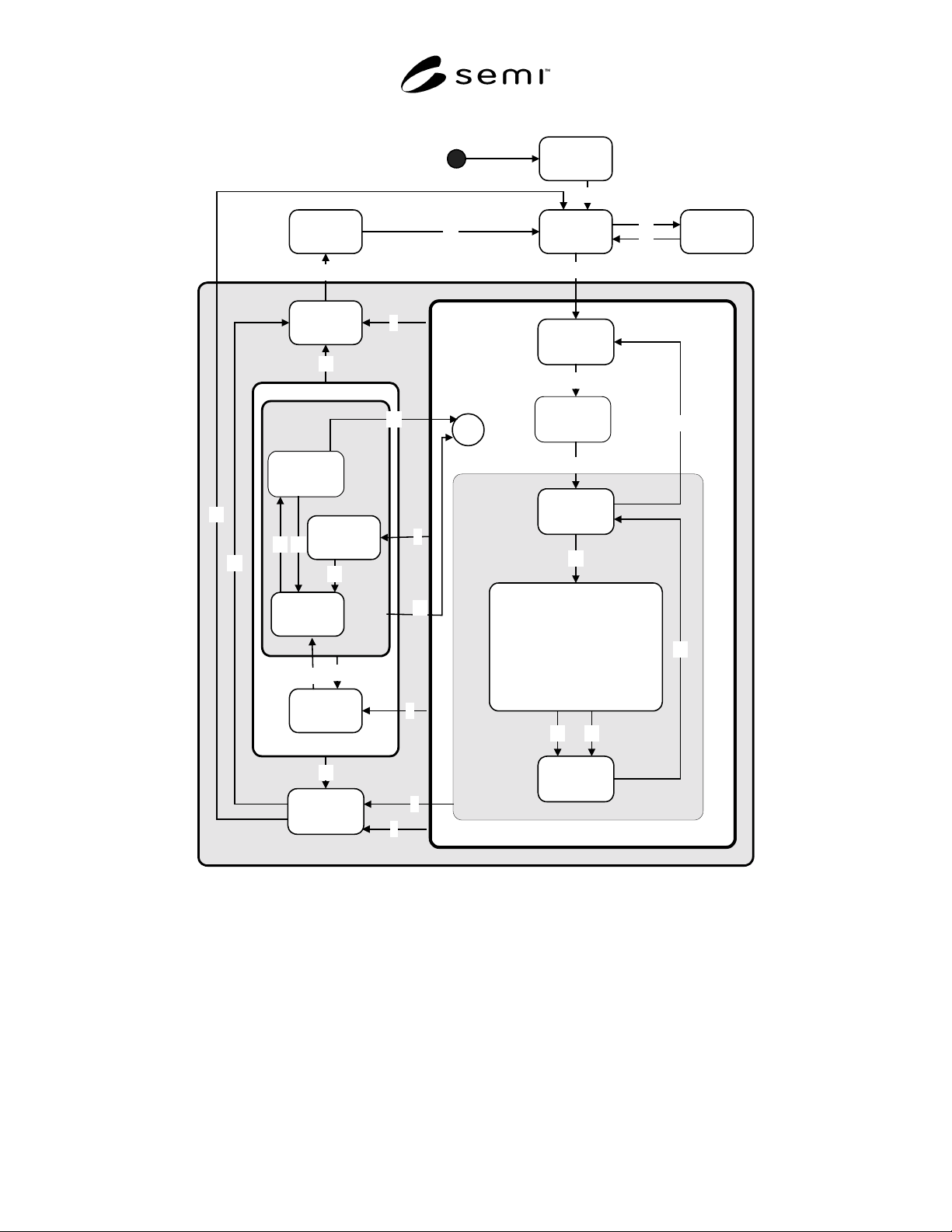
SEMI E30.5-0302 © SEMI 2001, 20023
INIT
IDLE with
Alarms
PROCESSING ACTIVE
IDLEABORTED
1
18
19
17
SETTING
UP
2
READY
WORKING
3
UNLOAD
4
25
23
24
EXECUTING
STOPPING
16
ABORTING
6
7
5
13
ALARM
PAUSED
PAUSED
22
21
H*
9
8
PAUSE
PROCESS
PAUSED
20
14
15
PROCESS
PAUSING
11
12
26
CHECKING
3233
10
38
LOAD
Figure 1
Generic MSEM Processing State Model Diagram