semi合集-English.pdf - 第628页
SEMI E84-0305 © SEMI 1999, 2005 26 L_REQ (P->A) READY (P->A) HO_AVB L (P->A) ES (P->A) VA (P->A) VS_0/1 (P->A) A M_AVBL (A->P) TR_R EQ (A->P) BUSY (A->P) COMPT (A->P) HO_AVBL is Confirmed OF…
SEMI E84-0305 © SEMI 1999, 2005 25
L_REQ
(P->A)
READY
(P->A)
HO_AVBL
(P->A)
ES
(P->A)
CS_0
(A->P)
CS_1
(A->P)
VALID
(A->P)
TR_REQ
(A->P)
BUSY
(A->P)
COMPT
(A->P)
CONT
(A->P)
HO_AVBL is
Confirmed
OFF
End of
Handshake
TD0
TA1
TP1
step numbers are
for reference only
1
2
5
4
7
8
9
6
10
3
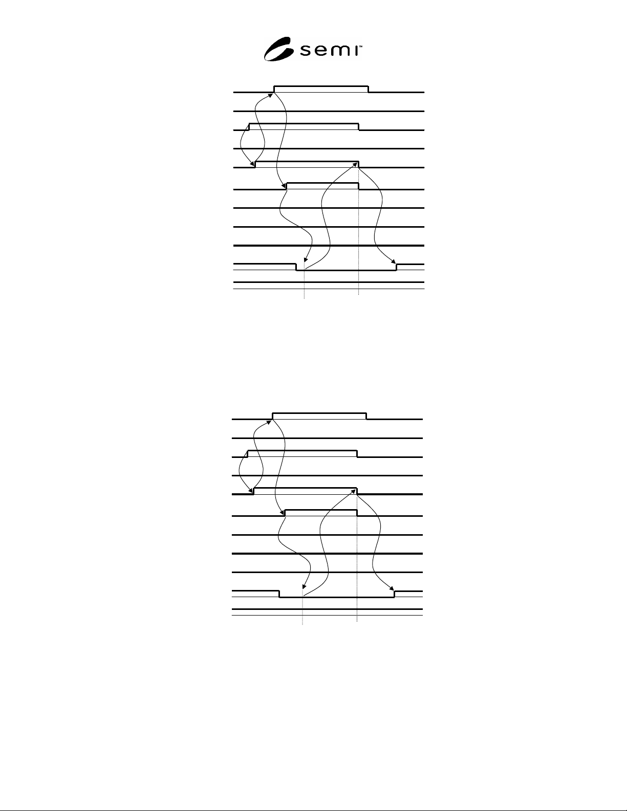
NOTE 1: The HO_AVBL signal turns OFF after the T_REQ signal is turned ON. The active equipment confirms the signal is
OFF in step 5.
Figure 25
Example of Handoff Available Signal
L_REQ
(P->A)
READY
(P->A)
HO_AVBL
(P->A)
ES
(P->A)
CS_0
(A->P)
CS_1
(A->P)
VALID
(A->P)
TR_REQ
(A->P)
BUSY
(A->P)
COMPT
(A->P)
CONT
(A->P)
HO_AVBL is
Confirmed
OFF
End of
Handshake
TD0
TA1
TP1
step numbers are
for reference only
1
2
3
5
4
7
8
9
6
10
NOTE 1: The HO_AVBL signal turns OFF after the L_REQ signal is turned ON. The active equipment confirms the signal is
OFF in step 5.
Figure 26
Example of Handoff Available Signal
SEMI E84-0305 © SEMI 1999, 2005 26
L_REQ
(P->A)
READY
(P->A)
HO_AVBL
(P->A)
ES
(P->A)
VA
(P->A)
VS_0/1
(P->A)
A
M_AVBL
(A->P)
TR_REQ
(A->P)
BUSY
(A->P)
COMPT
(A->P)
HO_AVBL is
Confirmed
OFF
End of
Handshake
step numbers are
for reference only
3
1
4
7
8
9
6
5
2
10
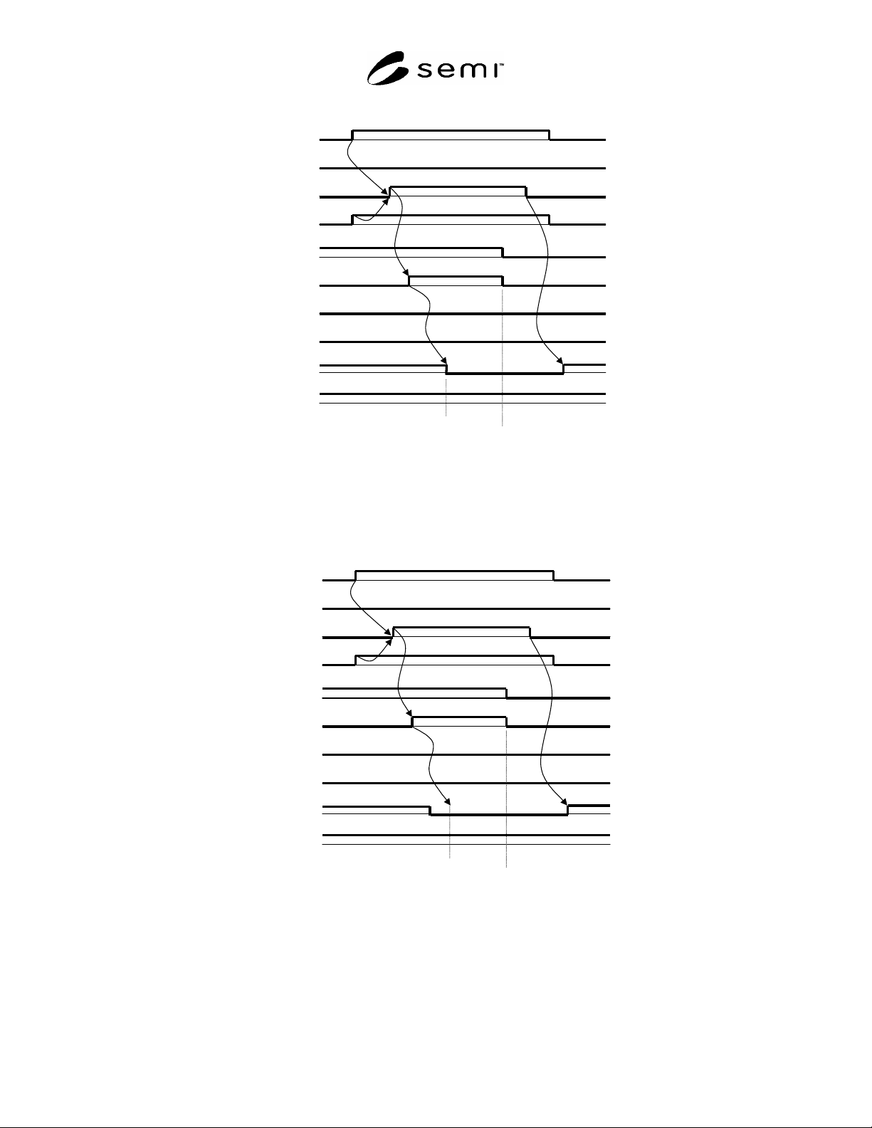
NOTE 1: The HO_AVBL signal turns OFF while the active equipment is confirming the signal in step 5.
Figure 27
Example of Handoff Available Signal
L_REQ
(P->A)
READY
(P->A)
HO_AVBL
(P->A)
ES
(P->A)
VA
(P->A)
VS_0/1
(P->A)
A
M_AVBL
(A->P)
TR_REQ
(A->P)
BUSY
(A->P)
COMPT
(A->P)
HO_AVBL is
Confirmed
OFF
End of
Handshake
step numbers are
for reference only
3
1
4
7
8
9
6
5
2
10
NOTE 1: The HO_AVBL signal turns OFF after the T_REQ signal is turned ON. The active equipment confirms the signal is
OFF in step 5.
Figure 28
Example of Handoff Available Signal
SEMI E84-0305 © SEMI 1999, 2005 27
L_REQ
(P->A)
READY
(P->A)
HO_AVBL
(P->A)
ES
(P->A)
VA
(P->A)
VS_0/1
(P->A)
A
M_AVBL
(A->P)
TR_REQ
(A->P)
BUSY
(A->P)
COMPT
(A->P)
HO_AVBL is
Confirmed
OFF
End of
Handshake
step numbers are
for reference only
3
1
4
7
8
9
6
5
2
10
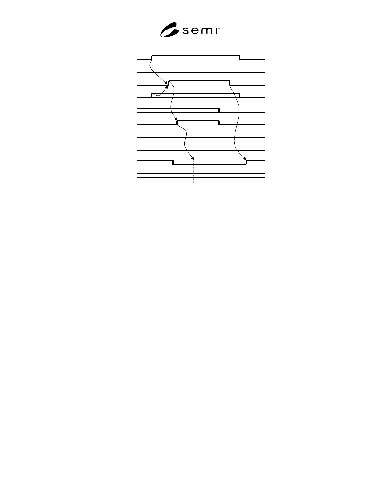
NOTE 1: The HO_AVBL signal turns OFF after the VA signal is turned ON. The active equipment confirms the signal is OFF in
step 5.
Figure 29
Example of Handoff Available Signal
6.3 Error Indication and Detection
6.3.1 Error Indication
6.3.1.1 To support operational reliability, this specification will define the following capabilities to indicate errors
on the interface:
a)
inform handoff unavailable which means the passive equipment (or passive OHS) is not available for material
handoff operation to the active equipment.
b)
inform emergency stop request to the active equipment (or active stocker).
c) inform handoff timeout error (see the Application Notes in Appendix 1 for examples of appropriate error
messages).
6.3.2 Error Detection
6.3.2.1 Interlock timeouts are required to detect handoff sequence error between the active and passive equipment.
This specification defines the interlock timeouts to be monitored by the active equipment and the passive equipment.
Table 7 shows the interlock timeouts for active equipment. Table 8 shows the timeouts for the passive equipment.
TAx (x is a number) represents the timer for the active equipment, and TPx (x is a number) represents the timer for
the passive equipment. The range for all timers (except TD0) shall be from 1 second to 999 seconds. All timer
setpoints shall be user programmable.
6.3.2.2
The delay timer specifies the delay time between VALID signals within one continuous sequence of
handoffs. Specifically, it signifies the delay following the VALID signal turning OFF on the completion of the first
handoff and the VALID signal turning ON at the start of the second handoff. The delay timer is required because
the passive equipment may need a certain time margin to detect the second VALID signal transition to ON. Table 9
shows the delay timer. All timer setpoints shall be user programmable.
6.3.2.3
The recommended and optional delay timer TD0 defines the timing between CS_0 or CS_1 ON and VALID
ON for the active equipment as shown in the signal time diagrams. In this way, the passive equipment can predict