semi合集-English.pdf - 第4389页
SEMI F96-0704 © SEMI 2004 1 SEMI F96-0704 SPECIFICATION FOR PORT CONF IGURATION OF CANISTERS TO CONTAIN LIQUID CVD PRECURSORS This specification was technically approved b y the Globa l Gases Com mittee and is the direct…
SEMI F95-0304
E
© SEMI 2004 7
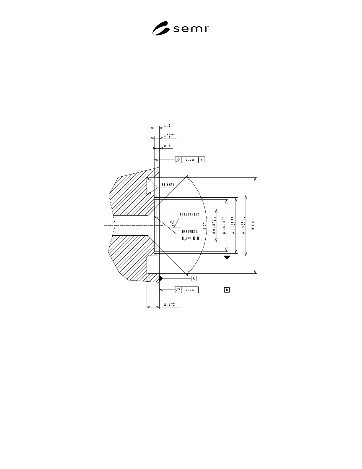
R1-4 Design Example 4
R1-4.1 Seal Design — See Figure R1-4.
R1-4.2 Surface Hardness — The sealing surface (the bottom of the counterbore) has a minimum hardness of 300
Vickers. The hardness may be tested per ISO 6507.
R1-4.3 Surface Roughness — The sealing surface (the bottom of the counterbore) has a surface roughness of 0.2
micrometers Ra max. The surface roughness may be tested per SEMI F37-0299.
R1-4.4 Surface Scratches — The sealing surface (the bottom of the counterbore) is without any lateral scratches
which are visible to non-magnified normal vision.
Figure R1-4
Design Example 4
NOTICE: SEMI makes no warranties or representations as to the suitability of the standards set forth herein for any
particular application. The determination of the suitability of the standard is solely the responsibility of the user.
Users are cautioned to refer to manufacturer' s instructions, product labels, product data sheets, and other relevant
literature, respecting any materials or equipment mentioned herein. These standards are subject to change without
notice.
By publication of this standard, Semiconductor Equipment and Materials International (SEMI) takes no position
respecting the validity of any patent rights or copyrights asserted in connection with any items mentioned in this
standard. Users of this standard are expressly advised that determination of any such patent rights or copyrights, and
the risk of infringement of such rights are entirely their own responsibility.
Copyright by SEMI® (Semiconductor Equipment and Materials
International), 3081 Zanker Road, San Jose, CA 95134. Reproduction o
f
the contents in whole or in part is forbidden without express written
consent of SEMI.
SEMI F96-0704 © SEMI 2004 1
SEMI F96-0704
SPECIFICATION FOR PORT CONFIGURATION OF CANISTERS TO
CONTAIN LIQUID CVD PRECURSORS
This specification was technically approved by the Global Gases Committee and is the direct responsibility of
the North American Gases Committee. Current edition approved by the North American Regional Standards
Committee on April 22, 2004. Initially available at www.semi.org June 2004; to be published July 2004.
1 Purpose
1.1 This document specifies the type, size and spacing
of connectors to be used on metal (e.g. stainless steel)
canisters for liquid chemical precursors, solutions and
solvents.
2 Scope
2.1 This document applies to metal (e.g. stainless steel)
canisters to be used for “liquid precursors” (see
definition) including solutions of precursors in solvents.
It also applies to containers for solvents used for in situ
cleaning of delivery system.
2.2 The liquid connection ports (inlet and outlet) are
included, as are pneumatic connections to valves.
2.3 Parameters such as overall canister dimensions are
expected to be specified by other standards.
NOTICE: This document does not purport to address
safety issues, if any, associated with its use. It is the
responsibility of the user of this standard to establish
appropriate safety and health practices and determine
the applicability of regulatory or other limitations prior
to use.
3 Referenced Standards
3.1 SEMI Standard
SEMI F66 — Specification for Port Marking and
Symbol of Stainless Steel Vessels for Liquid Chemicals
NOTICE: Unless otherwise indicated, all documents
cited shall be the latest published versions.
4 Terminology
4.1 Definitions
4.1.1 canister — a metal (usually stainless steel)
container in which a liquid precursor is supplied.
Canisters are also known as “ampoules”, “shuttle
drums”, “ tanks”, etc.
4.1.2 liquid precursor — a liquid precursor is a
chemical supplied as a liquid and used in Chemical
Vapor Deposition (CVD). Many liquid precursors are
toxic, reactive and air-sensitive.
5 Ports
5.1 A canister has a gas inlet port and a liquid outlet
port. The outlet port is equipped with a dip-tube,
marked according to SEMI F66. Note that a canister
may be used as a bubbler, by using the dip-tube port as
the gas inlet. In this standard however, liquid delivery
is assumed and the dip-tube port will be referred to as
the “outlet”.
5.2 Canisters up to 100 liters in volume:
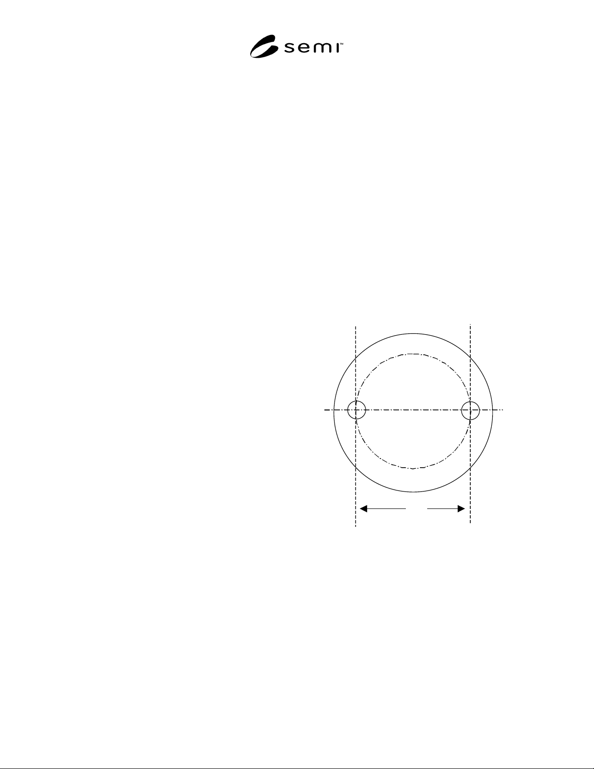
5.2.1 The ports will be located with the dip tube at the
3 o’clock position and the gas inlet at the 9 o’clock
position, as illustrated in Figure 1.
L
Figure 1
Port Configuration
5.2.2 Both ports shall be fitted with ¼” O.D. face-seal
connectors.
5.2.3 The port separation (L in the Figure) shall be
76 mm or 146 mm, + /- 4 mm, the value to be chosen
according to the diameter of the canister.
5.3 For canisters greater than 100 liters in volume, the
outlet port shall be in the center, the port separation 152
+ /- 4 mm, and the port connections ½” O.D. face-seal.
5.4 The connector shall be male on the gas inlet port
and female on the dip tube port.

SEMI F96-0704 © SEMI 2004 2
5.5 The height difference between the tops of the ports
will be no more than 0.5 mm.
5.6 Additional ports may be provided so long as they
do not interfere with the above specifications.
NOTE 1: The user of this standard should evaluate the
consequences of connecting a given precursor to a point
intended for other precursors. The nature of the precursor
itself and of the other precursors expected to be in use at the
same location should be taken into account. Consider
packaging precursors with a non-standard connector on the
canister outlet if necessary to avoid a dangerous situation.
6 Valves
6.1 The inlet and outlet port are each provided with a
valve but the details of those valves are not specified
here. If pneumatic valves are provided, the pneumatic
connection shall be a 1/8” quick-connect type.
NOTICE: SEMI makes no warranties or
representations as to the suitability of the standards set
forth herein for any particular application. The
determination of the suitability of the standard is solely
the responsibility of the user. Users are cautioned to
refer to manufacturer' s instructions, product labels,
product data sheets, and other relevant literature,
respecting any materials or equipment mentioned
herein. These standards are subject to change without
notice.
By publication of this standard, Semiconductor
Equipment and Materials International (SEMI) takes no
position respecting the validity of any patent rights or
copyrights asserted in connection with any items
mentioned in this standard. Users of this standard are
expressly advised that determination of any such patent
rights or copyrights, and the risk of infringement of
such rights are entirely their own responsibility.
Copyright by SEMI® (Semiconductor Equipment and Materials
International), 3081 Zanker Road, San Jose, CA 95134. Reproduction o
f
the contents in whole or in part is forbidden without express written
consent of SEMI.