semi合集-English.pdf - 第6045页
SEMI G4-0302 © SEMI 1982, 2002 9 Figure A1-3 Clamping Back Front R = 0.15 - 0.2 mm Fitted grooves to reduce slipping Figure A1-4 Inside of Cla m p ( Example)
SEMI G4-0302 © SEMI 1982, 2002 8
APPENDIX 1
TEST METHOD FOR LEAD BEND FATIGUE OF METAL STRIPS
NOTE: The material in this appendix is an official part of SEMI G4.
A1-1 Preface
This is related to the test method for lead bend fatigue
of metal strips of leadframe materials improving MIL-
STD-883. Results of this test suggest the lead bend
fatigue resistance of leadframes.
The following method is set up especially for the strips
with the thickness of 0.25 mm ± 0.008 mm.
A1-2 Method of Measurement
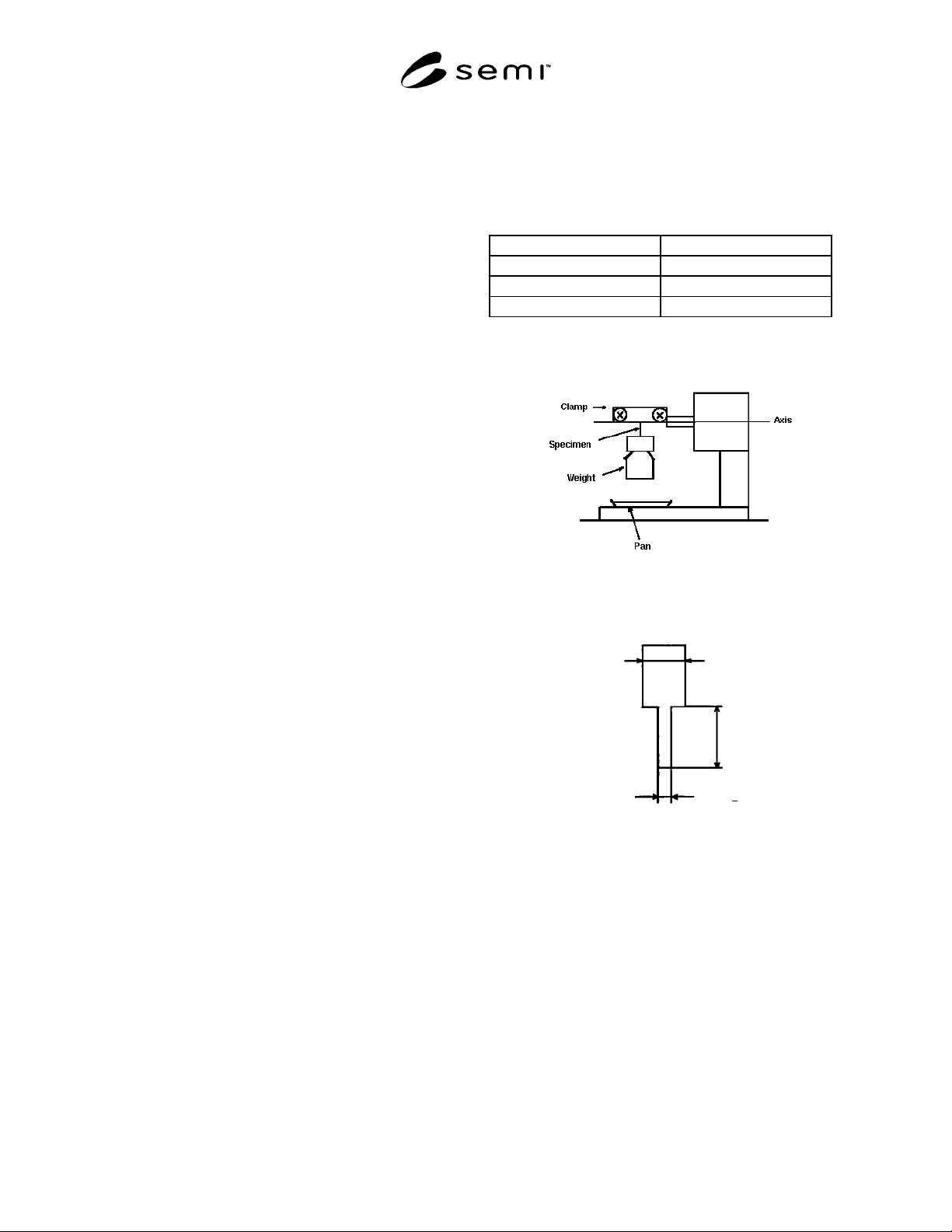
A1-2.1 Equipment — Automatic or manual lead bend
fatigue tester as shown in Figure A1-1.
A1-2.2 Preparation of Specimen — The specimen with
the width of 0.5 mm ± 0.05 mm is made by either
etching or stamping method. A wider portion on one
end is recommended for a good grip as shown in Figure
A1-2.
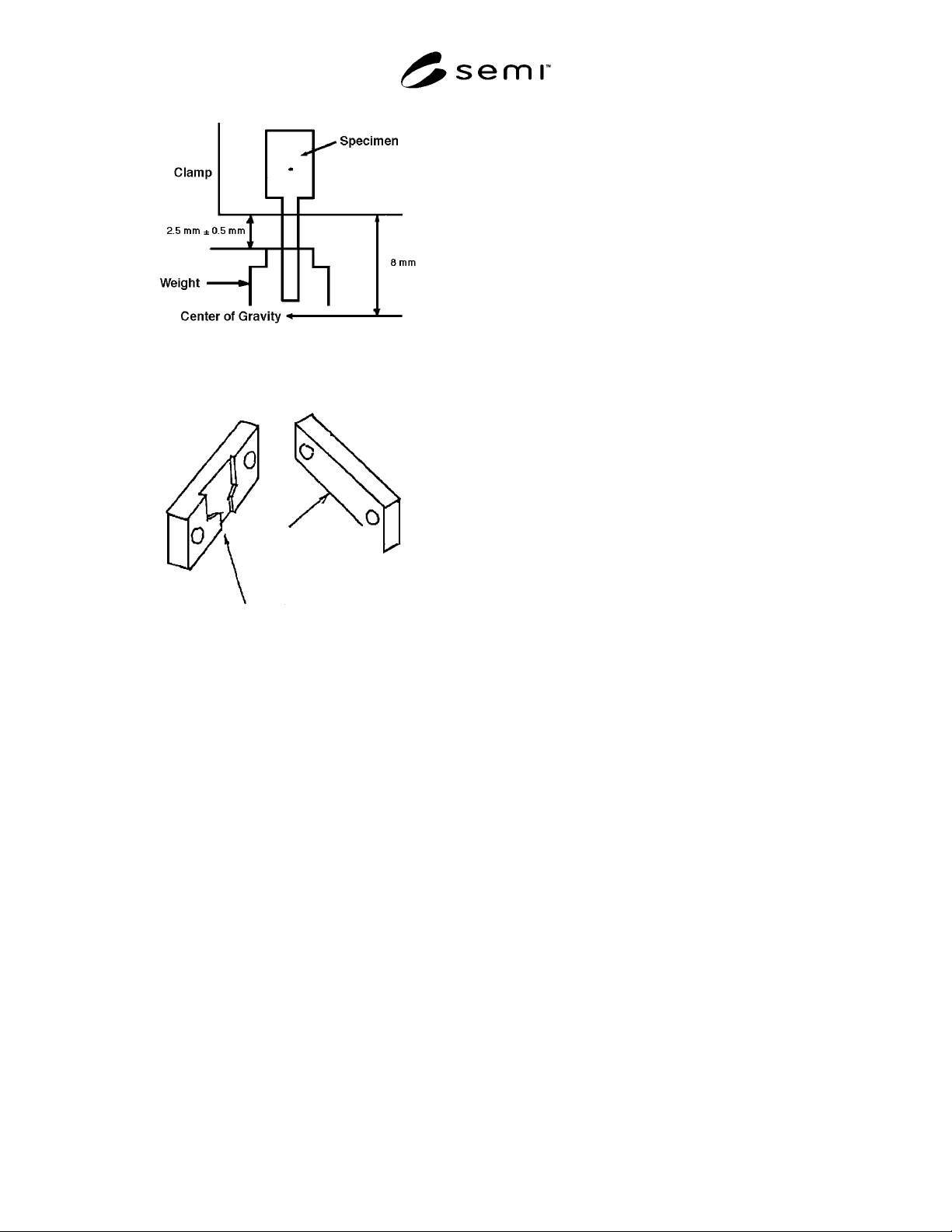
A1-2.3 Procedure — The specimen is clamped on both
ends with clamp and weight as shown in Figure A1-3
and tested under the conditions listed in Table A1-1.
The number of bending cycles (*) and other
information (**) should be recorded.
*The number of bending cycles: The cycles until
specimen breaks, and weight drops into pan.
0° – 90° – 0° bend on one side is counted as 1 cycle.
0° – 90° is counted as 0.5 cycle.
**Other information:
1. Rolling direction on the specimen.
2. Actually measured dimensional data of thickness
and width.
3. Burr side related to bending corner (for stamped
specimen only).
A1-3 Reference
SEMI G10 — Standard Method for Mechanical
Measurement of Plastic Package Leadframes
Table A1-1
Bend Angle (set) 90° ± 2°
Rate of Cycle 2–5 sec/cycle
Weight 2.206–2.452N (225–250 gf)
Bend Radius: R (see Fig. A4) 0.15–0.20 mm
Note 1: In other cross sectional areas (thickness and width) of
leads, the weight to be used shall be agreed upon between
supplier and purchaser.
Figure A1-1
Lead Bend Fatigue Tester
1.5 mm *
Arbitrary
0.5 mm +
0.05 mm
*Wide tip to reduce slipping
—
Figure A1-2
Shape of Specimen
SEMI G4-0302 © SEMI 1982, 2002 9
Figure A1-3
Clamping
Back
Front
R = 0.15 - 0.2 mm
Fitted grooves to reduce slipping
Figure A1-4
Inside of Clamp (Example)
SEMI G4-0302 © SEMI 1982, 2002 10
APPENDIX 2
TEST METHOD FOR SLITTER STRAIN OF STRIPS USED FOR
LEADFRAME STAMPING
NOTE: The material in this appendix is an official part of SEMI G4.
A2-1 Preface
This is related to the general evaluation method for
slitter strain of strips used for leadframe stamping. Such
distortion could result in adverse effects on leadframes,
such as coil set, lead twist, and camber.
A2-2 Evaluation Method
A2-2.1 Equipment — Tool microscope (×100).
A2-2.2 Procedure
A2-2.2.1 Collect flat samples approximately 150 mm
in length from strips in a way that residual distortion
can be overlooked. (Collection methods include wire
cutting, etching, refined cutting, etc.) Thickness of
samples should be either 0.25 mm, 0.20 mm, or 0.15
mm.
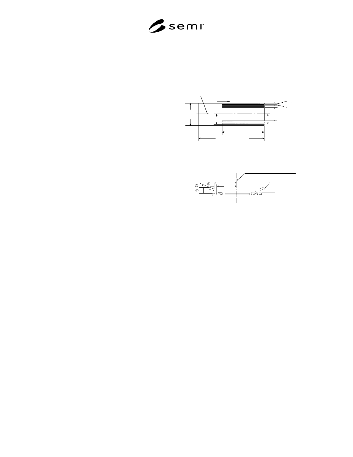
A2-2.2.2 Fashion each sample to the shape shown in
Figure A2-1 by etching or wire cutting. Measure with
the tool microscope to obtain coordinates of the leg end
corner. The reading accuracy is to 0.1 mm (see Note 1).
A2-2.2.3 Using the coordinates of the leg end corner,
for each leg obtain longitudinal curvature “A”, lead
twist “B”, and camber “C”, as shown in Figure A2-2
(see Note 2).
Note 1: Specify the direction of slit burr, and for legs in which
the longitudinal curvature A is reversed, measure by reversing
the sample itself.
Note 2: Measured values are marked as shown in Figure A2-
2.
Note 3: This method should be applied to only slitter strain.
Do not apply to any other kind of strain (e.g., thermal inner
strain).
Base line for
measuring camber
Slit direction
Strip
width
Approx. 150 mm
100 mm
5 mm min.
0.2 ~ 1 mm
2 +
0.5 mm
W
2W
2
Figure A2-1
Shape for Evaluation of Slitter Strain
Base line for measuring camber
Base line for measuring
longitudinal curvature A
Slit burr
Angle B
A
W
1
W
2
Figure A2-2
Evaluation Items