semi合集-English.pdf - 第702页
SEMI E92-0302 E © SEMI 1999, 2003 5 loading slider area should be op en z112 under the bottom interface planes. 7.4.3 Lo ader Locating Pins — Equipm ent must have two Loader locating pins to locate the box opener/loade r…

SEMI E92-0302
E
© SEMI 1999, 2003 4
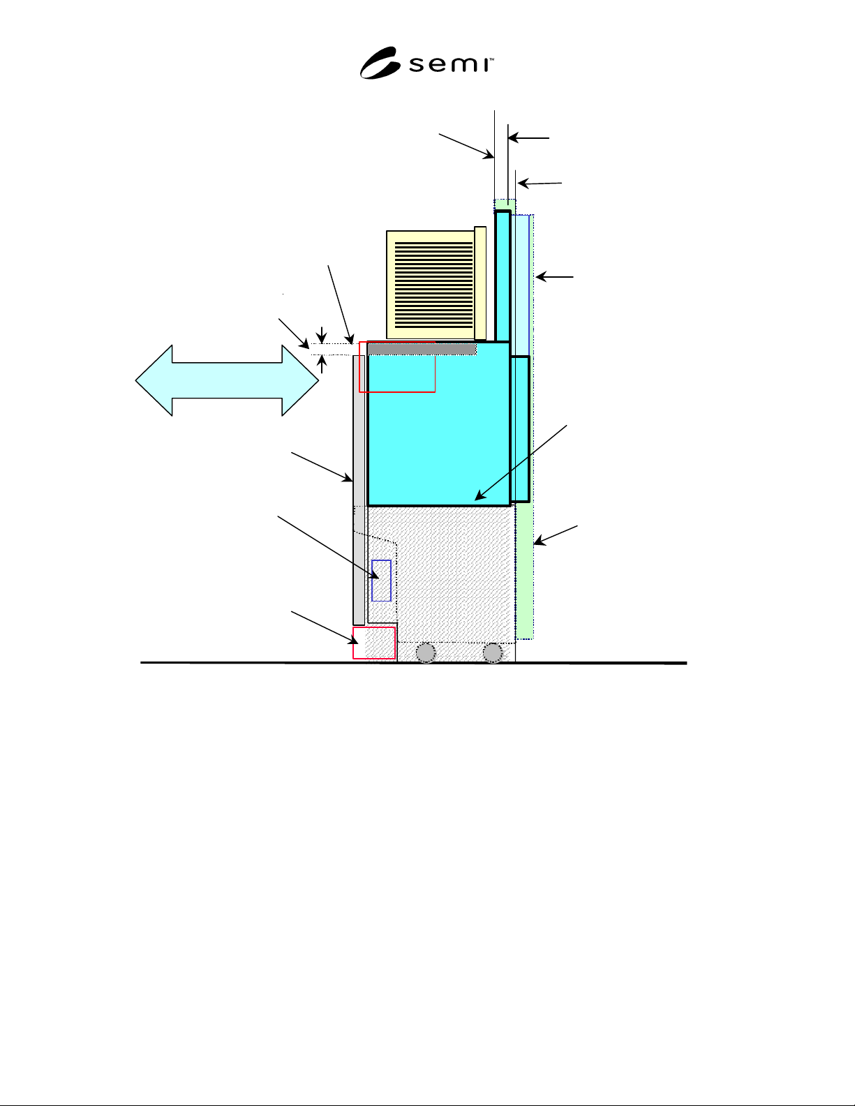
7.2 BOLTS/Light Exclusion Volume — Equipment or
loadport unit compliant with this standard must provide
a BOLTS/Light exclusion volume defined in this
section. BOLTS/Light exclusion volume consists of
multiple sub-volumes and spaces defined in this
section. The box opener/loader compliant with this
standard must be compatible with BOLTS/Light
exclusion volume. Bolts/Light exclusion volume is
shown in Figure 2.
7.2.1 Loader Exclusion Volume — Loader exclusion
volume is an exclusion volume for the main part of box
opener/loader that is defined by x108, y101, y110, y111,
and z107. y111 is intentionally shorter than SEMI
E15.1 D dimension in order to allow the equipment
integrators to place a safety door, a carrier ID
reader/writer, and/or any other features required by the
user. An additional removable cover can be mounted on
the box opener/loader if it is to be supplied as a
complete unit compliant with the SEMI E15.1 D
dimension.
7.2.2 Door Seal Exclusion Volume — Door seal
exclusion volume is an exclusion volume for the door
seal portion of box opener/loader that is defined by the
distance between the plane at the SEMI E15.1 D1 and
y101, x108, and z109.
7.2.3 BOLTS/Light Opening Exclusion Volume —
BOLTS/Light opening exclusion volume is an exclu-
sion volume for the box opener/loader encroachment of
equipment from BOLTS/Light plane at portion above
the permanent reserved space. There should be an
opening when the door is opened. Through this opening
substrates may be moved between the box on the
BOLTS/Light compliant box opener/loader and the
equipment by a wafer handler in the equipment.
BOLTS/Light opening exclusion volume is defined by
x102, y103, z103, and z108.
7.2.4 Permanent Reserved Space — Space that is
reserved permanently in the equipment defined by
x102, y102, z105, and z108.
7.2.5 Temporarily Reserved Space — Space that is
reserved temporarily during a door open/close motion is
being done and when the door is closed. The
temporarily reserved space during a door open/close is
defined by x102, y102, y103, z103, and z108. The
temporarily reserved space when a door is closed is
defined by x102, y103, y112, z103, and z108.
7.2.6 The Loader Bottom Flange Exclusion Volume —
The loader bottom flange exclusion volume is an
exclusion volume for fixing the box opener/loader to
bottom interface plane. Loader bottom flanges are
located on the both bottom side of the box
opener/loader and directly mounted on bottom interface
plane. The loader bottom flange exclusion volume is
defined by x108, x109, y115, y116, and z113 measured
from the bottom end of z107.
NOTE 3: The spaces to access the fixing bolt should be
reserved by equipment side. This document does not define
these spaces.
7.3 Side Interface Features — This standard defines
the equipment side of the side interface features. Side
interface features are defined with respect to “Docked
facial datum plane” instead of “Facial datum plane”.
The box opener/loader should mate with these features
to provide the seal to the equipment. The side interface
features are shown in Figure 2.
7.3.1 BOLTS/Light Plane — The BOLTS/Light plane
is defined to be parallel to and at a distance y101 from
the docked facial datum plane. The Seal Zone is on this
plane.
7.3.2 Cycle-to-Cycle Repeatability — The cycle-to-
cycle repeatability of y101 must be within y113.
7.3.3 Seal Zone — The equipment side of the
BOLTS/Light plane specified by x101, x103, z101,
z102, z104, and z106 must be a flat area for sealing
between the equipment and the box opener/loader.
7.3.3.1 The flatness of the seal zone must be within
y114 and the perpendicularity of the seal zone to the
facial and horizontal datum planes must be within
σ1
.
7.3.3.2 This standard only defines the seal zone on the
equipment side. The actual seal is not defined in this
standard, but should be mounted on the box
opener/loader.
7.3.4 Wafer Position — This standard defines a typical
wafer position when the box opener/loader positions the
wafers to the equipment. The facial datum plane of a
docked carrier is defined by y110 from the facial datum
plane. This provides compatible wafer center positions
from the facial datum plane.
NOTE 4: This means that this standard defines a specified
typical docking stroke.
7.4 Bottom Interface Features — This standard defines
mainly the equipment side of the bottom interface
features. Bottom Interface Features are shown in
Figure 3.
7.4.1 Regarding the box opener/loader, parallelism of
the bottom interface feature and the horizontal datum
plane must be within
σ2
.
7.4.2 Bottom Interface Planes — The Bottom Interface
Feature should have two Bottom Interface Planes
defined by x104, x105, y104, y105, and z107. Nothing
other than locating pins can protrude above these
planes. During maintenance, the front end of the

SEMI E92-0302
E
© SEMI 1999, 2003 5
loading slider area should be open z112 under the
bottom interface planes.
7.4.3 Loader Locating Pins — Equipment must have
two Loader locating pins to locate the box
opener/loader so as to provide highly repeatable and
quick attachment/detachment. Horizontal locations of
the loader locating pins are defined by x106 and y106.
Height of the loader locating pins is defined by z110.
Diameter of the loader locating pins is defined by d1.
A box opener/loader compatible with this standard must
refer these two Loader Locating pins.
7.4.3.1 Positioning Pin — Loader locating pin on the
left side from operator is a positioning pin that is used
to hold box opener/loader both in x and y directions.
7.4.3.2 Anti-Rotation Pin — Loader locating pin on the
right side from operator is an anti-rotation pin that is
used to hold box opener/loader in y direction only (see
Figure 4).
7.4.4 Locking Screws — Four locking screws defined
by x106, y107, and y108 to tighten the box
opener/loader.
7.4.4.1 The equipment should have M8-16 tapped
holes at these locations.
7.4.5 Control Connection Area — Area used to pass
connectors, wires, and tubes for electrical signals,
power supply and other inlets/outlets.
7.4.5.1 The control connection area is defined at the
same height as the the bottom interface planes by x107
and y109.
NOTE 5: This standard only defines the connection area for
the box opener/loader itself. It is recommended that
connectors will be located above this area for quick
maintainability.
7.4.5.2 Other connections which will possibly be
located in this area for other functions are listed below
and may be defined in separate standards:
• Carrier ID reader/writer head interface (automated
units that read or write to an ID tag defined in
SEMI E15.1)
• Manual operation panel
• Wafer mapper
7.5 Panel Interface Height — This standard defines an
optional panel interface height so as to provide panel
installation height to enclose box opener/loader in the
equipment. Panel interface height is defined by z111
from horizontal datum plane. In case this option is
used, both equipment and the box opener/loader should
have forklifts exclusion volume defined by SEMI E15.1
H0.
SEMI E92-0302
E
© SEMI 1999, 2003 6
SEMI E15.1 Compatible Equipment
Boundary
SEMI E84
Forklifts exclusion volume
Reduce Reserved
Space
Parallel I/O for AMHS
Communication
BOLTS/M Plane
BOLTS/M image
(Adopter)
Cart to SEMI E15.1
Docking Interface Port
BOLTS/Light Plane
SEMI E15.1 Compliant Load
Port Height
Equipment panel
Slide In/Out
CIDRW
BOLTS/
Light
BOLTS/Light
Shelf
Bottom interface
plane
Figure 1
Diagram Concept of Light-Weight and Compact Box Opener/Loader and Tool-Interoperability Standard
(BOLTS/Light)