semi合集-English.pdf - 第2668页
SEMI E96-1101 © SEMI 1999 , 2001 8 ways b y which be havio ral variat io n withi n an asp ect can be model ed: Param eters and Variants . 6.3.13 Paramete rized Aspect s An aspect can have parameters. Differen ce s in p…
SEMI E96-1101 © SEMI 1999, 20017
Architecture
4
(Chapter 15, “Interworking Architecture,”
Chapter 16, “Mapping COM to CORBA,” and Chapter
17, “Mapping OLE Automation to CORBA”) defines
mapping approaches covering:
Interface Mapping,
Interface Composition Mapping, and
Identity Mapping.
6.3.5 These areas should be addressed in order to pro-
vide a mapping between the OMG IDL used to specify
CIM Framework interfaces and the message bus used
for implementation. If the mapping is not specific (i.e.,
can occur in multiple ways) then two implementations
may not necessarily be able to communicate even if
they use the same message bus type. Although the
CORBA Interworking Architecture is specific to
Microsoft technologies, it could provide the foundation
for future interworking mappings.
6.3.6 The current CIM Framework interfaces are
specified in OMG IDL. The interfaces can be directly
compiled and used with any of the available ORB
implementations on the market.
6.3.7 The only way to provide such a direct solution
using Microsoft DCOM would be to create additional
CIM Framework interface specifications in DCOM
MIDL and/or OLE Automation ODL. This would allow
direct support for message bus functionality using
DCOM. For example, the CIM Framework memory
management requirement of “in” for parameter passing
(see Section 6.3.15) would be directly supported by
MIDL and DCOM but since the CORBA exception
model is significantly richer than the DCOM exception
model, mapping CORBA exceptions to COM would
require an additional protocol to be defined for DCOM.
6.3.8 The CORBA Interworking Architecture supports
mapping the current CIM Framework interfaces defined
in OMG IDL to DCOM MIDL or OLE Automation
ODL. This mapping is detailed enough that the map-
ping should always provide the same MIDL/ODL solu-
tion. Even though the current scope does not include
interoperability between implementations on DCOM
and CORBA (see Section 3.2), the issue of mapping the
interface is still the same. This would also provide a
step towards true interoperability using CORBA/
DCOM bridge products that are beginning to become
available.
6.3.9 Microsoft also provides an extension called OLE
Automation. These interfaces are described in Object
Definition Language (ODL). The OLE interfaces can be
invoked dynamically by a client with no compile-time
interface knowledge. The OLE data types are a subset
of the types supported in DCOM, and there is no sup-
port for user-defined constructed types. The mapping
solution differs for the DCOM and the OLE Automa-
tion. OLE Automation does not provide as clean a map-
ping from OMG IDL as DCOM does. This limitation
may not allow some of the interfaces to translate com-
pletely to an OLE Automation implementation. Thus,
component suppliers using an OLE Automation imple-
mentation should explain impact on interfaces that were
not fully supported due to the Automation restrictions.
6.3.10 The CORBA Interworking Architecture covers
mapping issues for the major areas of concern for the
CIM Framework. The areas of primary importance are
the Interface mapping, Interface composition mapping,
Identity mapping, and Exception mapping. The
CORBA Interworking Architecture gives detailed map-
pings for each of these areas and deals with the DCOM
and OLE Automation mappings separately. The follow-
ing five subsections summarize these mapping issues.
6.3.11 Interface Mapping
6.3.11.1 The OMG IDL primitives, constructed data
types, and object references map closely to DCOM. The
inherited CORBA interfaces may be represented as
multiple DCOM interfaces. The CORBA attributes may
be mapped to get and set operations in DCOM
interfaces.
6.3.11.2 The OMG IDL primitives map to OLE
primitives except for special cases. The OLE interfaces
do not support constructed data types and should be
mapped to specially constructed interfaces. CORBA
object references map to OLE Automation interface
pointers. There are difficulties in mapping CORBA
multiple inheritance to OLE Automation interfaces
documented in the CORBA specification.
4
CORBA
attributes may be mapped to get and set operations in
OLE Automation interfaces.
6.3.12 Aspects The total behavior of a piece of a
productive entity in a factory can be viewed as the
union of distinct behaviors. Each such isolated behavior
(or functional area) is called an aspect of the productive
entity.
6.3.12.1 There is great variety in productive entity
behavior. There are generic aspects that are shared by
all or most productive entities (such as recipe
management or process state model or material
tracking) and there are aspects that are specific to one
productive entity type or to a particular productive
entity model. The behavior of each productive entity is
the union of the particular aspects of that productive
entity.
6.3.12.2 Saying that two pieces of productive entities
have a certain aspect does not necessarily mean that
they behave absolutely the same way. There are two

SEMI E96-1101 © SEMI 1999, 2001 8
ways by which behavioral variation within an aspect
can be modeled: Parameters and Variants.
6.3.13 Parameterized Aspects An aspect can have
parameters. Differences in productive entities behavior
are modeled by assigning different values to the
parameters. For example if a physical structure aspect
of the productive entity specifies that the productive
entity has a material buffer, the number of material
units (buffer size) that can be placed on the buffer is a
possible parameter. The number of buffers the
productive entity has can be another parameter.
6.3.14 Variants While parameterization is a very
powerful tool, there are variations in behavior that
cannot be simply modeled as different parameter
values. In this case one can use variants. An aspect is
said to have variants if there are some different
behaviors related to the same aspect. For example the
process control aspect can have a discrete variant and a
continuous variant. In the discrete variant the
productive entity processes discrete units of material
(like the material within a magazine or a single wafer
carrier), while in the continuous variant the productive
entity processes continuously as long as there is
material to be processed.
6.3.14.1 Differences between productive entities are
best modeled as parameters when possible in order to
avoid an explosion of the number of variants, while at
the same time trying to maintain the clarity of the
model.
6.3.14.2 A complete specification of the behavior of a
piece of productive entity should specify variants for
these aspects that have them.
6.3.15 Where do aspects and variants come from?
They leverage on previous work done by the industry.
GEM (Generic Equipment Model, SEMI E30) is a
primary source for identifying generic aspects. Various
SEMs (Specific Equipment Models) are a source for
specific aspects and very likely for variants. Other
SEMI standards like SEMI E-40 (Standard For
Processing Management) cover other aspects neglected
by GEM.
6.3.16 Specifying Productive Entity Interfaces in a
Factory In order to specify the interface of a
productive entity it is necessary first to identify the
aspects (or variants of these aspects) supported by the
productive entity, then to specify the interfaces
associated with each aspect. The productive entity
interface specification is then the sum of the interface
specifications for all participating aspects.
6.3.16.1 The interface of an aspect (or variants of these
aspects) is the sum of its Queries, Commands, Event
Notifications and Service Requests and thus the
problem of defining productive entity interface is
reduced to the problem of defining the interfaces of
individual aspects (or variants of these aspects).
6.3.17 Architecture The productive entity in a
factory is viewed as a composition of its aspects. The
total productive entity behavior is therefore represented
by the sum of all its aspects representing these
behaviors. Each aspect specifies a specific behavior of
productive entity and provides an interface for
incoming messages (queries and commands).
6.3.17.1 An aspect has a name. The productive entity
can answer a reference to one of its aspects given the
aspect name:
AspectInterface aspectNamed(in string
aspectName);
6.3.17.2 An AspectInterface is a virtual interface that
represents a generic aspect. All aspect interfaces inherit
from the generic AspectInterface. When an aspect has
variants, the aspect interface itself is virtual, and all its
variant interfaces inherit from it.
6.3.17.3 Additionally the productive entity answers a
list of the names of all its aspects:
StringList allAspectNames();
6.3.17.4 The usual scenario for a client is to acquire a
reference to the productive entity. It then acquires
references to the productive entity aspects of interest by
querying the productive entity. The client then invokes
methods on the aspect interfaces as required.
6.3.17.5 The client only needs to acquire aspect
interfaces once when it first establishes communication
with the productive entity. From then on it caches the
productive entity interface as well as the references to
the productive entity aspects for further use. The
procedure of acquiring references needs to be repeated
only in case the references become invalid (due to
productive entity restart for example).
6.3.18 How To Add A New Aspect The definition of
an aspect follows the following aspect definition
pattern. It includes the following items:
6.3.18.1 Aspect Name Each aspect has a name that
identifies it.
6.3.18.2 Aspect Description The aspect description
explains the productive entity behavior covered by the
aspect. If the aspect has been derived from an existing
standard, the description includes a reference to this
standard. It explains the concepts and the used
terminology, adds state models and state transition
diagrams if required, and explains the interactions
between the productive entity and the factory elements
related to the aspect. If the interactions require certain
sequences of messages, they are also described (as use
cases or interaction diagrams).
SEMI E96-1101 © SEMI 1999, 20019
6.3.18.3 The description also includes all the side
effects and exceptions that can occur as a result of the
interactions related to the aspect.
6.3.18.4 If the aspect has any relation or effects related
to other aspects, they are also described here.
6.3.19 Variants If the aspect has variants, each
variant is named and described.
6.3.19.1 IDL Usually the IDL will include a special
module for the aspect. The module includes data type
definitions specific to the aspect and usually a single
interface that provides the various queries and
commands of the aspect. An aspect that has variants has
an interface per variant. The interfaces for the variants
can be inherited from a common (abstract) aspect
interface.
6.3.19.1.1 An aspect that deals with service requests
should also include an IDL definition for the server that
provides the services. Which is to be done in a separate
module.
6.3.19.2 Aspect Definition Example Here the
Control State Aspect has been chosen as an example for
aspect definition.
6.3.19.2.1 Aspect Name Control State
6.3.19.2.2 Aspect Description The definition of the
Control State Aspect is based on Generic Equipment
Model (GEM) SEMI standard E30.
NOTE 2: The state diagram presented here is simpler than the
one in SEMI E30, since the internal sub-states are irrelevant
to the productive entity interface, and the concept of HOST
OFFLNE is obsolete in a distributed factory environment
6.3.19.2.2.1 The control state model defines the level
of cooperation between the productive entity and the
factory. It also specifies how the operator interacts in
the different levels of factory control.
6.3.19.2.2.2 The control state model provides the
factory with three levels of control over the productive
entity:
6.3.19.2.3 OFFLINE In the OFFLINE state,
operation of the productive entity is done by the
operator. In the OFFLINE state the productive entity
accepts a query to find out the current control state and
the command to change its control state, but rejects all
other queries or commands (raising the rejected
exception). While in the OFFLINE state the productive
entity produces no events and no service requests.
6.3.19.2.4 LOCAL In the LOCAL state the
productive entity is operated by the operator.
6.3.19.2.4.1 In the LOCAL state the productive entity
answers all queries from the factory and allows the
factory to execute a limited set of commands. The
commands that are prohibited are those that cause
movement or directly affect the process. The productive
entity sends events and asks for services from the
factory.
6.3.19.2.5 REMOTE In the REMOTE state the
productive entity is controlled by the factory. The
factory has full access to all the necessary commands to
operate the productive entity through the full process
cycle in an automated manner. The degree of
automation can vary from productive entity to
productive entity and from factory to factory. Generally
operators are required to intervene in setup operations,
operator assist situations, etc. Therefore when in
REMOTE state, even though theoretically fully under
control of the factory, the productive entity should not
restrict the operator from executing essential operations
such as selecting a recipe, pausing or resuming the
process, operator assists, material movement to/from
the productive entity, initiating recipe download and
other productive entity specific commands on a
command by command basis as needed. At the very
least the operator should be able to change the control
state, actuate an emergency stop and interrupt
processing (stop, abort or pause).
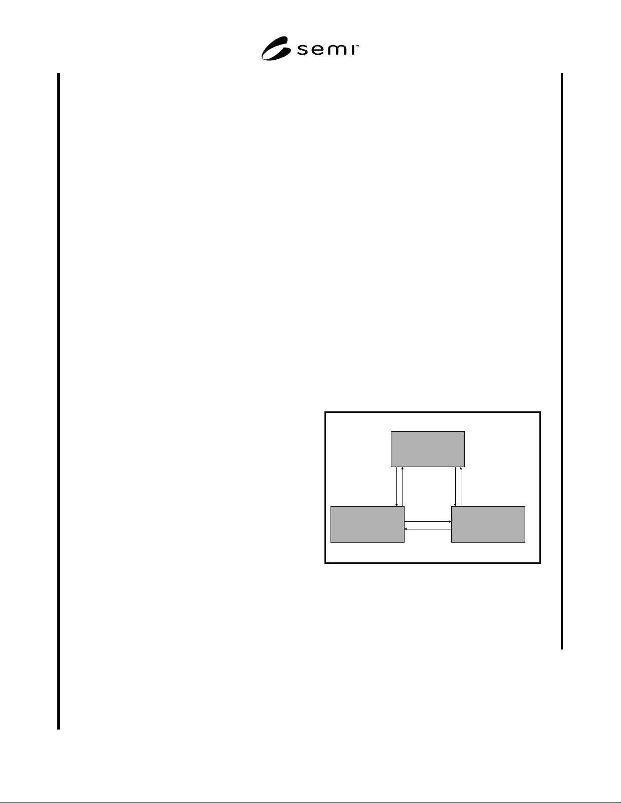
6.3.19.2.6 The following diagram depicts the
productive entity Control State model.
OFFLINE
LOCAL REMOTE
12 3 4
5
6
Figure 1
6.3.19.2.7 As can be seen from the diagram, transition
from any state is allowed to the two others. The aspect
provides the factory methods for querying the current
state, for initiating a transition to any of the states, and
for events when state transitions occur.