semi合集-English.pdf - 第500页
SEMI E72-0600 © SEMI 2003 2 4.1.2 depth — the horizontal dimension perpe ndicular to the loa d face plane. 4.1.3 easement space — t he floor space that m ust remain clear to th e rear a nd sides of the equi pment (but no…
SEMI E72-0600 © SEMI 1998, 2005 1
SEMI E72-0600 (Reapproved 0305)
SPECIFICATION AND GUIDE FOR 300 mm EQUIPMENT FOOTPRINT,
HEIGHT, AND WEIGHT
This specification was technically approved by the Global Physical Interfaces & Carriers Committee and is
the direct responsibility of the North American Physical Interfaces & Carriers Committee. Current edition
approved by the North American Regional Standards Committee on December 10, 2004. Initially available
at www.semi.org February 2005; to be published March 2005. Originally published in 1998, previously
published June 2000.
1 Purpose
1.1 Currently, device manufacturers cannot easily plan or retrofit their fabs, because equipment volumes are not
predictable. Similarly, equipment suppliers cannot predict fab designs, because there are too many configurations. In
general, fab space is not used efficiently, and there seems to be a trade-off between space efficiency and
maintainability. This standard is a guide for equipment design and a specification for maximum limits on equipment
volume and weight.
2 Scope
2.1 This standard specifies limits on the footprint, height, and weight of equipment for 300 mm fabs. Separate limits
are given for the parts of the equipment in the main fab and in the sub-fab. Separate limits are also given for the
equipment after it is installed and for the components of the equipment as it is moved into the fab. The actual
footprint may vary by equipment type.
2.2 This standard is intended to set an appropriate level of specification that places minimal limits on supplier
innovation while ensuring opportunities for users to be globally (though possibly not locally) efficient with
equipment volumes.
2.3 This standard does not purport to address safety issues, if any, associated with its use. It is the responsibility of
the users of this standard to establish appropriate safety and health practices and determine the applicability of
regulatory limitations prior to use.
NOTICE: This standard does not purport to address safety issues, if any, associated with its use. It is the
responsibility of the users of this standard to establish appropriate safety and health practices and determine the
applicability of regulatory or other limitations prior to use.
3 Referenced Standards
3.1 SEMI Standards
SEMI E15 — Specification for Tool Load Port
SEMI E15.1 — Specification for 300 mm Tool Load Port
NOTICE: Unless otherwise indicated, all documents cited shall be the latest published versions.
4 Terminology
4.1 Definitions
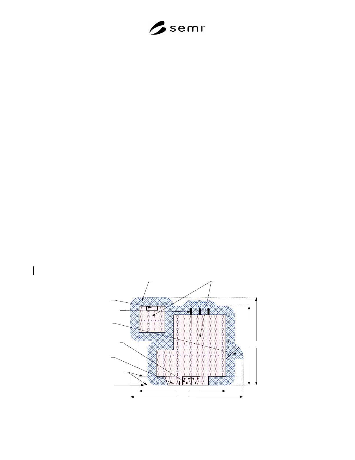
4.1.1 cost footprint — the area (A) of the smallest horizontal rectangle that contains all of the shadow footprint and
half of the easement space around the equipment (for use as the floor space metric in Cost of Ownership
calculations). As shown in Figure 1, this is computed as
A = [Wt + ½ (Ws – Wt)] × [Dt + ½ (Ds – Dt)]
= ¼ (Wt + Ws) × (Dt + Ds)
Where W represents width and D represents depth

SEMI E72-0600 © SEMI 2003 2
4.1.2 depth — the horizontal dimension perpendicular to the load face plane.
4.1.3 easement space — the floor space that must remain clear to the rear and sides of the equipment (but not in
front of the load face plane). This includes safety aisles, ergonomic maintenance access space, component removal
space, and room for doors to swing out (see Figure 1).
4.1.4 load face plane — the furthest physical vertical boundary plane from the cassette centroid or carrier centroid
on the side (or sides) of the tool where loading of the tool is intended (as defined in SEMI E15).
4.1.5 shadow footprint — the area of the floor space directly under every part of the equipment during its operation
(see Figure 1). This includes any temporary projections from the equipment during loading or processing (such as
carriers that stick out from the equipment or equipment load ports that protrude only when the equipment is being
loaded).
4.1.6 width — the horizontal dimension parallel to the load face plane.
5 Requirements and Recommendations
NOTE 1: The dimensions cited in the following sections are specified in Table 1.
5.1 Sub-Fab vs. Main Fab Footprint
5.1.1 Requirements — Both the cost footprint and the shadow footprint of the remote parts of any equipment in the
sub-fab must be less than or equal to the cost footprint and the shadow footprint (respectively) of the parts of that
equipment in the main fab (the cleanroom including both bays and chases, if any). Furthermore, the remote parts of
the equipment in the sub-fab must be capable of being installed so that the rectangle defining the cost footprint in the
sub-fab is entirely underneath the rectangle defining the cost footprint in the main fab. In some fab designs (such as
slab on grade), there is no sub-fab (or basement). In such cases, these requirements apply to the remote parts of the
equipment in whichever equipment support area contains the same remote parts of the equipment as a sub-fab. Also,
some fabs have multiple sub-fab levels. In such cases, these requirements apply to the remote parts of the equipment
in all sub-fab levels.
5.1.2 Recommendations — Since the sub-fab is likely to have more columns than the main fab, it is recommended
that the remote parts of the equipment in the sub-fab come in modules that can be arranged to accommodate a
variety of layouts.
5.2 Equipment Height
5.2.1 Requirements — The maximum height of any equipment (other than a stocker) must be less than or equal to H
in the main fab and Hs in the sub-fab. Any connections for utilities and required overhead mainten-ance access must
also be included within these limits. These limits also apply during installation, so if a part of the equipment must be
rotated up into place, the diagonal measurement must be less than these limits.
5.2.2 Recommendations — Thus, equipment suppliers are advised to not plan on ceilings higher than these limits.
5.3 Floor Loading
5.3.1 Requirements — The maximum mass of any equipment in the main fab divided by its shadow footprint must
be less than or equal to M (except when support pedestals are used). Furthermore, the maximum weight on any 0.6
m by 0.6 m (2 ft. by 2 ft.) floor tile (in any installation configuration) must be less than or equal to Mt. These limits
also apply when the equipment is being moved into the fab and installed, unless spreader plates are used.
5.3.2 Recommendations — It is recommended that seismic loading also be considered when designing equipment
weight distribution.
5.4 Move-In-Size
5.4.1 Requirements — To clarify the size of the doors and hallways needed in the fab, this paragraph specifies the
size of the equipment's components after it has been uncrated, while it is being moved into the fab, and before it is
installed. All parts of the equipment destined for the main fab must come in packages that are no taller than Z and
that are smaller than X by Y in two orthogonal horizontal dimensions. All parts of the equipment destined for the
sub-fab must come in packages that are no taller than Zs and that are smaller than Xs by Ys in two orthogonal
SEMI E72-0600 © SEMI 1998, 2005 3
horizontal dimensions. Furthermore, none of these packages may weigh more than Mm each. This paragraph does
not apply to stockers and AMHS transport equipment.
5.4.2 Recommendations — Equipment suppliers and device manufacturers might also consider carrier stocker size,
move-in timing, and move-in path during stocker and facility design. Equipment that conforms to these limits may
still be too large to fit into standard truck trailers or aircraft cargo bays.
5.5 Maintenance Access
5.5.1 Requirements — To avoid interfering with carrier transport systems, equipment must not require regularly
scheduled maintenance from the front. This requirement does not apply to maintenance performed on user
interfaces, cart-docking interfaces, load ports, carrier buffers, and load locks.
5.5.2 Recommendations — It is recommended that as little regularly scheduled maintenance as possible be required
from the side.
5.6 Width vs. Depth
5.6.1 Recommendations — In general, to minimize the number of bays required in a fab, it is recommended that
equipment be designed to minimize width rather than depth.
5.7 Linked Equipment
5.7.1 Recommendations — To make linked equipment (such as cluster tools or steppers with litho tracks) jointly
space efficient, it is recommended that they be designed to minimize the cost footprint of the entire system as a
whole.
6 Related Documents
6.1 SEMI Standards
SEMI E6 — Facilities Interface Specifications Guideline and Format
SEMI E26.1 — Radial Cluster Tool Footprint 300 mm Standard
SEMI E35 — Cost of Ownership for Semiconductor Manufacturing Equipment Metrics
SEMI E76 — Guide for 300 mm Process Equipment Points of Connection to Facility Services
SEMI S2 — Safety Guidelines for Semiconductor Manufacturing Equipment
NOTICE: Unless otherwise indicated, all documents cited shall be the latest published versions.
rear user
interface
utilities supply
access door
swing-out
E15.1-compliant
load ports and
carrier buffers
front user
interface
possible wall
locations, if any
(see SEMI 15.1)
load face plane
of the tool
Wt
Ws
Dt Ds
easement space
(required space
around the tool)
shadow footprint
(includes all
parts of the tool)
Figure 1
Equipment Footprint Dimensions