semi合集-English.pdf - 第1416页
SEMI E30-1103 © SEMI 1992, 2003 90 calibration. The need for calibrati on is a non-linear function of the number of wafers processed in that chamber. A status variable exists which contains the number of wafers processed…
SEMI E30-1103 © SEMI 1992, 2003
89
A.7 Examples of Limits Monitoring
A7.1 Introduction
A7.1.1 Four limits monitoring examples are included
below to help clarify the use of limits and to illustrate
typical applications. The first example shows how to
apply limits to boolean values. The second illustrates
application of several limits to a floating point variable
in a classical control zone style. The third example
shows an integer counter variable used to prompt for
equipment maintenance.
A7.2 Examples
A7.2.1 Example 1 –– Valve Monitoring
A7.2.1.1 The ACME Shine-Um-Rite Model 13
includes a sump which contains the chemical agent
used to clean bare wafers. A chemical feeder system
serves to refill the sump when the level drops below a
certain level. The fill is accomplished via an on-off
value driven by sensors in the sump. Facilities must be
informed of the proportion of the time the valve is open
(approximates usage) and any time the value remains
open for more than 5 minutes (valve likely broken).
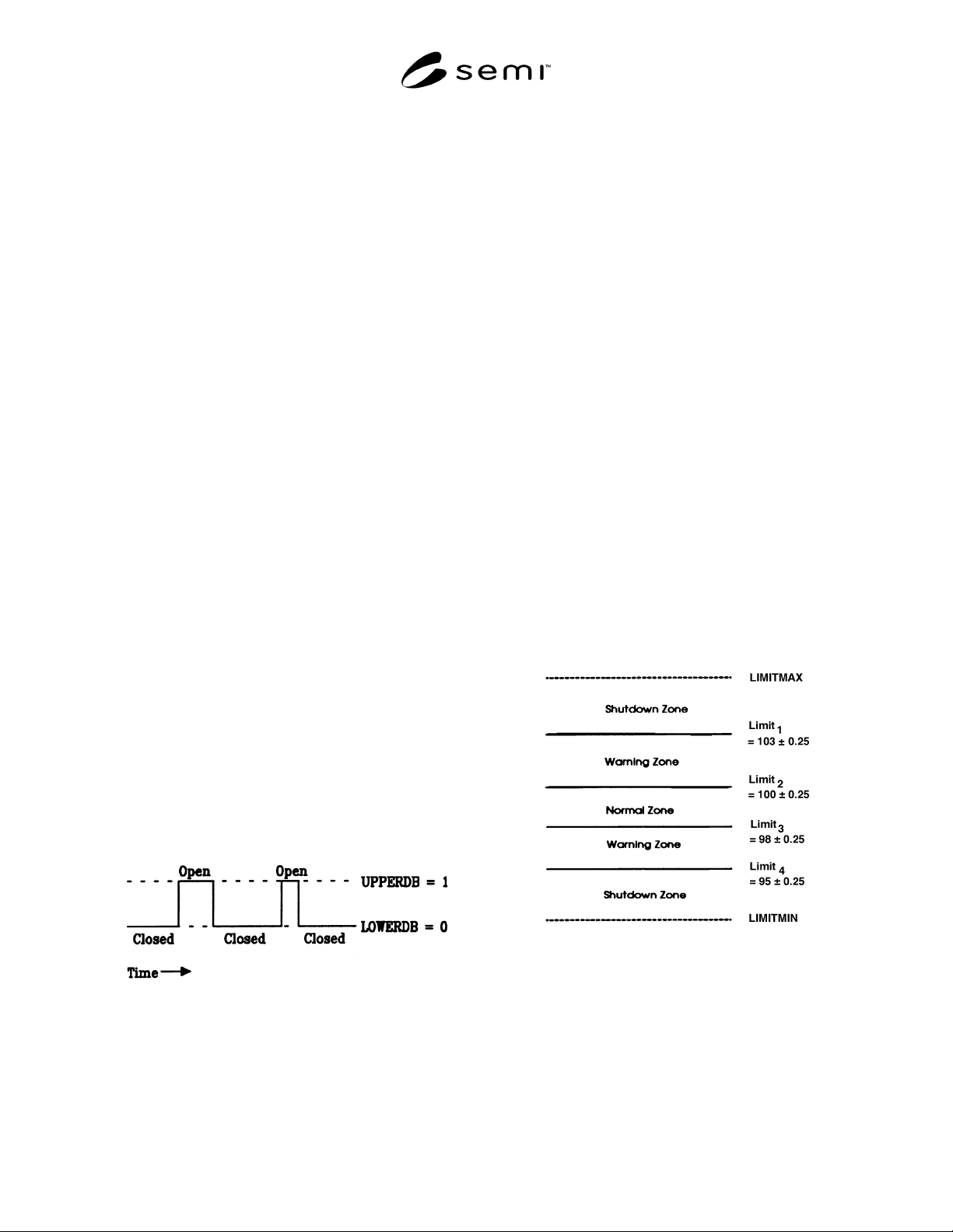
A7.2.1.2 To implement this requirement, a limit was
defined for the Boolean status variable which contains
the current state of the valve (i.e., 0 = Closed, 1 =
Open). See Figure A7.1 for illustration. LIMITID1 was
defined with UPPERDB = LIMITMAX = 1 (Open) and
LOWERDB = LIMITMIN = 0 (Closed). As a result,
any time the valve opens, a collection event is
generated with TransitionType = 0 and when the valve
closes, a collection event is generated with
TransitionType = 1. An event report containing the
DVVAL LimitVariable was attached to each collection
event and reporting for the event was enabled.
NOTE: Boolean values are defined as 0 =
False/Closed/Off and any value > 0 = True/Open/On ––
never depend on a value of 1.
Figure A7.1
Valve Monitoring Example
A7.2.2 Example 2 –– Environment Monitoring
A7.2.2.1 ACME also makes a Model 2 Stepper. The
environmental control system of this equipment is
designed to hold the internal temperature relatively
constant, but is sensitive to large changes in the
external environment, opening of access doors, etc. To
ensure that processing conditions are appropriate, the
internal stepper temperature is monitored to ensure it
remains in a safe operating zone (within “Shutdown”
limits). In addition, a second set of limits are used
within the Shutdown limits to bound the “Normal”
operating range. Frequent excursions from the normal
range into the “warning” range will prompt service on
the environmental control system. The target
temperature range is specified as 98–100° , the
shutdown limits as 95–103° .
A7.2.2.2 Event reports are desired when the internal
temperature moves outside of the normal operating
zone into a warning zone (above or below), when the
temperature moves back into the normal operating zone
from the warning zones, and when the temperature
moves out of the warning zones into the shutdown
zones. Furthermore, temperature fluctuations of 0.5°
should not trigger multiple event reports.
A7.2.2.3 Probably the most intuitive use of the limits
monitoring capability is in establishing normal,
warning, and shutdown zones for a particular
equipment variable. Limits may be combined to provide
such a scenario. The method is described below and
illustrated in Figure A7.2. Please note that in the figure,
limits are denoted as solid lines for simplicity, with
deadbands indicated using the ± notation.
Figure A7.2
Environment Monitoring Example
A7.2.3 Example 3 –– Calibration Counter
A7.2.3.1 Another ACME equipment is the multi-
chamber Duz-It-All Model 7. This machine includes
redundant chambers to increase throughput. One
particular chamber on this equipment requires periodic
SEMI E30-1103 © SEMI 1992, 2003
90
calibration. The need for calibration is a non-linear
function of the number of wafers processed in that
chamber. A status variable exists which contains the
number of wafers processed since the last calibration
was performed. Maintenance is definitely required after
every 8 cycles, but the machine must be checked after 5
and 7 cycles to determine whether early calibration is
necessary. This checking may be done by examining
certain other equipment status variables.
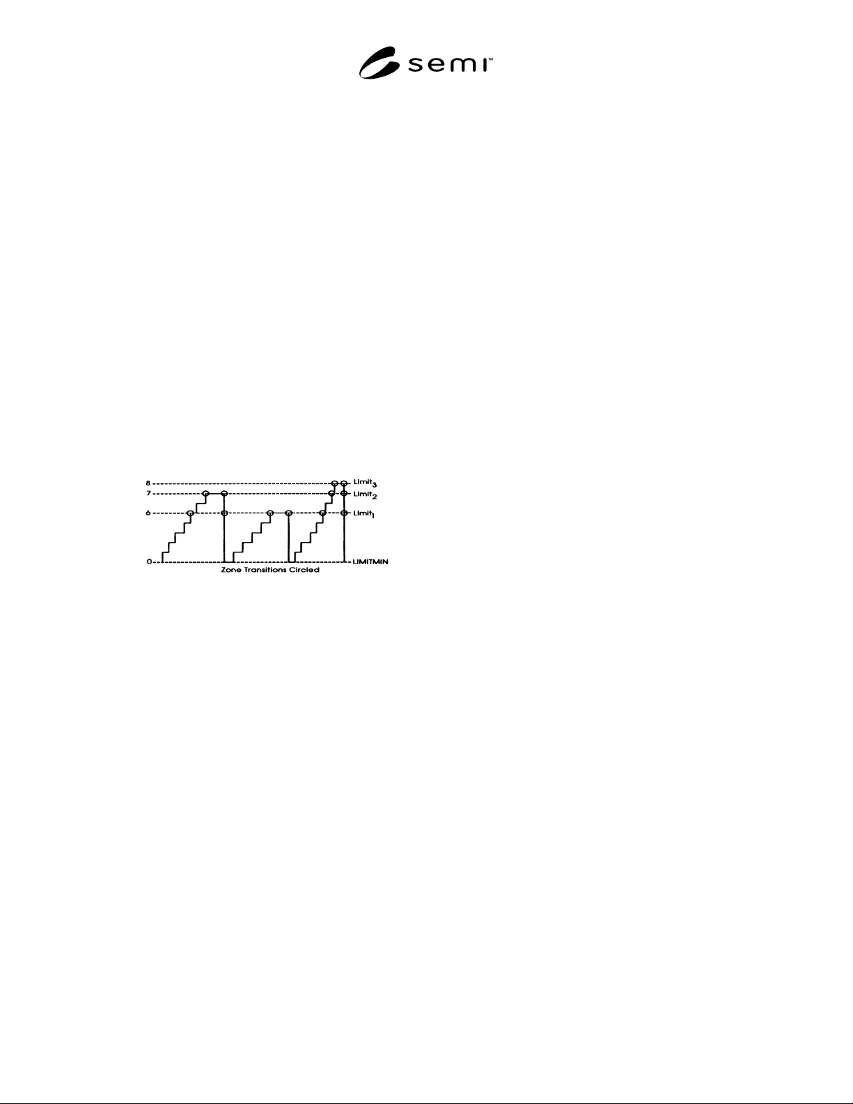
A7.2.3.2 To meet this need, three limits are defined for
the counter variable. Three limits were set, at 5, 7, and
8. Deadbands are set to zero, since chattering is not a
problem. All the pertinent information is placed in an
event report which is attached to the CEID for the
limits of the counter to negate the need for further
message exchange. Event reports are generated as each
limit is reached (one zone transition each), and when
the counter is reset following calibration (one, two, or
three zone transitions referenced in one report). Figure
A7.3 illustrates this example. Note that disabling the
report upon counter reset (downward transitions) is not
possible.
Figure A7.3
Calibration Counter Example
A7.2.4 Example 4 –– Derived Variables
A7.2.4.1 The flagship of the ACME line is the new
HotDog Furnace. This is a vertical furnace which
exposes wafers to a variety of temperatures during
processing. The temperature profile during the run is
critical to the process and is typically contains a number
of plateau’s at different levels during the run. The
owner wishes to monitor the temperature and be alerted
whenever the actual temperature profile differs from the
ideal by > 0.5° . The derived variable was created to
provide a steady target range during the run, no matter
what the desired temperature range happened to be.
Deviation from “ideal temperature profile” was chosen
as the new variable to be monitored. The equipment
already had access to the profile for the run, which
described the desired temperature at a given time into
the process. The manufacturer added a calculation each
time the actual temperature was sampled, subtracting
the ideal temperature from the actual. They provided as
status variables the actual temperature, the ideal
temperature, and the new “deviation from profile”
variable. One limit was activated and set to 0.5 degrees
and a second set to –0.5 degrees (each with a deadband
width of 0.05). Thus, when the temperature deviation
from setpoint exceeds ± 0.5, an event is generated
containing the current desired temperature and the
actual temperature. For good measure, additional data
was added, providing time since start of run to
document the precise point in the process that the
problem occurred.
A7.2.4.2 In order to achieve the desired behavior, the
host defines four monitoring limits. Two of the limits
establish the target zone. These are responsible for
reporting transitions from normal to warning zones in
either direction. The other two limits establish the
transitions between the warning zones and the error
zones. The difference between UPPERDB and
LOWERDB for each limit is 0.5. This may also be
expressed as limit ± 0.25. Combining limits does not
change the way the equipment treats limits monitoring,
but rather builds a method of interpreting limits from
the host’s point of view.
A.8 Process Parameter Modification for
Process and Equipment Control
A8.1 Introduction
A8.1.1 In many equipment control applications there is
a need for a GEM host to modify one or a small set of
process parameters associated with a recipe. The
number of parameters modified, frequency of
modification (e.g., wafer-to-wafer, batch-to-batch, etc.),
range of modification, etc., is largely a function of the
equipment control application. Utilizing GEM, at least
two methods are envisioned for modifying process
parameters on a tool. With the first method,
“Equipment Constants” can be used to relate process
parameters of the updated recipe. Equipment Constants
can also be used in a mode where they relate suggested
modifications to process parameters from the stored
recipe, i.e., the constants contain only the + /-
differential from a nominal value. The former mode is
preferred because it better ensures data integrity
between the controller and tool. With the second
method the entire recipe could be downloaded, but this
results in an enormous amount of communication
overhead. Note that, in all cases, the Equipment
Constants do not replace the process parameters inside
a recipe, but are associated with (e.g., linked to) these
parameters to relate modifications. The remainder of
this application note provides a description of how
process parameter modification can be implemented
using existing GEM capabilities. The method may be
used in a GEM compliant system provided that the
specific GEM capabilities described are supported.

SEMI E30-1103 © SEMI 1992, 2003
91
A8.2 Equipment Constants
A8.2.1 Incremental process parameter modification for
process and equipment control can be supported over a
GEM interface by using the Equipment Constants GEM
capability (see Section 4.5). With this capability, each
process parameter (or process parameter at a step) that
can be modified, e.g., for purposes of process control,
is associated with an equipment constant. Using the
Equipment Constant GEM scenarios (see Section 4.5.5)
the host can (1), send process parameters or parameter
modifications, (2), request current values of modifiable
recipe parameters, (3), retrieve name lists of equipment
constants associated with modifiable parameters, and
(4), be informed by the equipment when an operator
changes one of the modifiable process parameters.
A8.2.2 The equipment constants should represent the
actual values of the process parameters with which they
are associated. Depending on the equipment operation
and control application, the equipment constant could
represent the actual value of a process parameter at a
recipe step, or over the entire recipe. The equipment
constants could also be utilized to represent the
differentials of process parameters from nominal
values. However it is important to note that, when
using differential values to relate process parameter
modifications, any loss of synchronization between
equipment and host could result in an incorrect
assessment of the value of a process setpoint by the
host. Note also that, upon system startup, and whenever
the appropriate process parameters are modified, the
equipment constants should also be modified as
necessary to always reflect the (absolute or relative)
values of the associated process parameters.
A8.2.3 In order to maintain synchronization between
equipment and host, it is recommended that equipment
constants associated with recipe parameters be applied
to only override the currently selected and active recipe.
A selected recipe is considered to be active whenever
the equipment is in the “PROCESSING” state and the
recipe is the currently selected recipe (process
program). If multiple recipes are utilized during one
process event, e.g., cluster tool scenario, it is
recommended that separate equipment constants be
utilized for each recipe/process parameter pair.
A8.2.4 Note that timing and traceability issues
associated with utilizing the equipment constants
capability (for process control) are application specific
and beyond the scope of this application note.
Equipment that provides for recipe parameter overrides
though setting of Equipment Contstants should also
provide additional Equipment Constants for the set that
includes the name of the associated process program
and a Boolean variable to enable and disable the
override feature. In addition, the supplier should
document for each parameter: (1), the associated
Equipment Constant, and (2), any restrictions on the
state (active or not) or the recipe in which the parameter
may be modified. Also, since override of the process
setpoints may be provided by a Host controller
application element, it is recommended that the
equipment provide an event report whenever the
associated recipe has been modified.
A8.3 Example
A8.3.1 In the example of Figure A.8.1, a Chemical-
Mechanical Planarizer (CMP) single wafer “polishing”
system includes a GEM compliant planarizer
(equipment), a thickness metrology unit and a (host)
controller. The tool polishes a wafer to a target
thickness. The post-process thickness is measured by
the metrology unit and reported to the host controller.
The controller utilizes a feedback control algorithm to
determine the appropriate polish “time” recipe
parameter for the next wafer. This time should be
reported to the CMP equipment utilizing the
equipment’s GEM interface so that the information can
be utilized for the next wafer processing event.
A8.3.2 The mechanism described in this application
note could be utilized to implement process control as
follows. A settable equipment constant is associated or
“linked” with the “time” parameter on the equipment.
Equipment system documentation indicates the linkage
and the conditions under which the linkage is valid.
When the controller determines an appropriate “time”
parameter value for the next wafer to be polished, it sets
the equipment constant to this value (see Section 4.5).
The equipment is configured to accept this equipment
constant change and, if the equipment is in (or possibly
when the equipment reaches) the appropriate state, the
recipe parameter is modified.