semi合集-English.pdf - 第414页
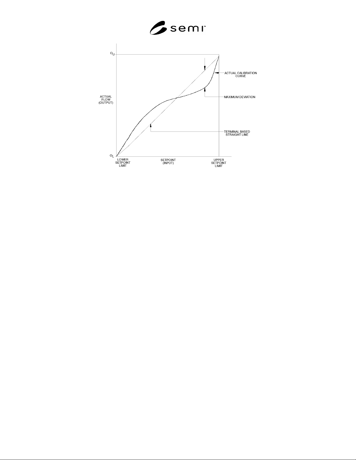
SEMI E56-1104 © SEMI 1996, 2004 3 Figure 1 Terminal-Based Linearity for Mass Flow Contr oller 5.2.14 hysteresis — that prope rty of an element evidenced by the depe ndence of the value of the output, for a given excur si…

SEMI E56-1104 © SEMI 1996, 2004 2
5.1.12 DBS — deadband of setpoint
5.1.13 D
l
— lower deadband value
5.1.14 D
u
— upper deadband value
5.1.15 DUT — device under test
5.1.16 FS — full scale flow rate
5.1.17 HD — hysteresis of device
5.1.18 HDBS — hysteresis plus deadband at a setpoint
5.1.19 HS — hysteresis at a setpoint
5.1.20 i — reading number in a cycle for a given set-
point
5.1.21 I — intermediate value
5.1.22 j — cycle for a given setpoint
5.1.23 k — up cycle number for a given setpoint
5.1.24 kPa — kilopascal
5.1.25 LD — linearity of DUT
5.1.26 LS — linearity of setpoint
5.1.27 m — slope
5.1.28 m — down cycle number for a setpoint
5.1.29 n — number of up scale readings
5.1.30 NC — normally closed
5.1.31 n
j
— number of readings at a setpoint at a given
cycle
5.1.32 NO — normally open
5.1.33 P — precision
5.1.34 psia — pounds per square inch absolute
5.1.35 RPD — repeatability of the DUT
5.1.36 RPS — repeatability at a setpoint
5.1.37 S — setpoint
5.1.38 S
a
— average of setpoint
5.1.39 sccm — standard cubic centimeters per minute
5.1.40 S
l
— setpoint, down cycle
5.1.41 S
u
— setpoint, up cycle
5.1.42 slm — standard liters per minute
5.1.43 SRD — short-term reproducibility of the device
5.1.44 SRS — short-term reproducibility at a setpoint
5.1.45 v
i
— the ith measured value at a setpoint for a
given cycle
5.1.46 Y — ideal linearity value
5.1.47 Z — zero offset of DUT
5.1.48 Z
a
— indicated flow at zero actual flow
5.2 Definitions
5.2.1 accuracy — the closeness of agreement between
an observed value and the true value; the total
uncertainty of an observed value, including both
precision and bias.
5.2.2 accuracy curve — the curve fitted through the
average measured values over the specified range of the
device under test.
5.2.3 accuracy device — the total uncertainty over a
specified range of the device. Device accuracy over a
range is stated as the worst case accuracy taken over all
tested setpoints in this range.
5.2.4 actual flow — the gas flow as measured by an
external standard, not the electrical output of a mass
flow meter.
5.2.5 bias — the difference, at a setpoint, between the
measured value and the sum of the setpoint value and
the zero offset. The measured values of a flow standard
include its total uncertainty.
5.2.6 cardinal setpoint — a specific setpoint to assess
the accuracy of the device under test (DUT). For this
test method, the cardinal setpoints are 10%, 20%, 30%,
40%, 50%, 60%, 70%, 80%, 90%, and 100% of full
scale.
5.2.7 deadband — the range through which a setpoint
may be varied, upon reversal of direction, without
initiating an observable change in output signal.
5.2.8 device under test — mass flow device is being
tested by this method.
5.2.9 downscale reading — a reading approached from
a setpoint greater than the current setpoint and beyond
the deadband.
5.2.10 downscale value, average — the sum of all
downscale readings, in one cycle, at a single setpoint,
divided by the number of these values.
5.2.11 drift — the change in output over a specified
time period for a constant input under specified
reference operating conditions.
5.2.12 drift, long-term — the drift between a series of
tests over a specified time interval. This specified time
interval is generally much greater than the time
necessary to run an individual test.
5.2.13 drift, short-term — the drift between sets of
measurements over the duration of the test.
SEMI E56-1104 © SEMI 1996, 2004 3
Figure 1
Terminal-Based Linearity for Mass Flow Controller
5.2.14 hysteresis — that property of an element
evidenced by the dependence of the value of the output,
for a given excursion of the input, upon the history of
the prior excursions and the direction of the current
traverse.
5.2.15 indicated flow — flow indicated by MFC under
test. Electrical output of the DUT.
5.2.16 linearity — the closeness to which a curve
approximates a straight line.
5.2.17 linearity, terminal-based — the maximum
absolute value of the deviation of the accuracy curve
(average of upscale and downscale values) from a
straight line through the upper and lower setpoint limits
of the accuracy curve (see Figure 1).
5.2.18 measured value — the actual flow through a
device under test, expressed in sccm or slm, as
measured by a standard, preferably primary.
5.2.19 measured value, average — the sum of all
readings (both upscale and downscale) for all cycles, at
a single setpoint, divided by the number of these
readings.
5.2.20 operating conditions, normal — the range of
operating conditions within which a device is designed
to operate and for which operating influences are stated
[ISA S51.1].
5.2.21 operating conditions, reference — the range of
operating conditions of a device within which operating
influences are negligible [ISA S51.1].
5.2.22 operating influence — the change in a
performance characteristic caused by a change in a
specified operating condition from reference operating
conditions, all other conditions being held within the
limits of reference operating conditions [ISA S51.1].
5.2.23 pneumatic noise — localized, random variations
in pressure and flow.
5.2.24 precision — the closeness of agreement among
the measured values at a setpoint. It is often expressed
as a standard deviation.
5.2.25 repeatability — the closeness of agreement
among a number of measured values at a setpoint,
under the same operating conditions, operator,
apparatus, laboratory, and short intervals of time. It is
usually measured as a nonrepeatability and expressed as
a repeatability in percent of reading.
5.2.26 reproducibility — the closeness of agreement
among repeated measured values at a setpoint, within
the specified reference operating conditions, made over
a specified period of time, approached from both
directions. Reproducibility includes hysteresis,
deadband, long-term drift, and short-term
reproducibility.
NOTE 1: Between repeated measurements, the input may
vary over the range, and operating conditions may vary within
normal operating conditions.
5.2.27 reproducibility, short-term — the closeness of
agreement among a number of measured values at a
setpoint, under the same operating conditions, operator,
apparatus, laboratory and short intervals of time,
approached from both directions. The approach must
SEMI E56-1104 © SEMI 1996, 2004 4
be from beyond the deadband. Short-term
reproducibility includes repeatability, hysteresis,
deadband, and short-term drift.
5.2.28 setpoint — the input signal provided to achieve
a desired flow, reported as sccm, slm, or percent-full
scale.
5.2.29 setpoint limit, lower — the lowest setpoint at
which the instrument is specified to operate.
5.2.30 setpoint limit, upper — the highest setpoint at
which the instrument is specified to operate, usually full
scale.
5.2.31 settling time — the time between the set point
step change and when the actual flow remains within
the specified band (see SEMI E17).
5.2.32 span — the full-scale range of the DUT.
5.2.33 stability — the ability of a condition to exhibit
only natural, random variation in the absence of
unnatural, assignable-cause variation.
5.2.34 standard conditions — 101.32 kPa, 0.0°C (14.7
psia, 32°F)
5.2.35 uncertainty, total — the range within which the
true value of the measured quantity can be expected to
fit; an indication of the variability associated with a
measured value that takes into account the two major
components of error, bias and the random error
attributed to the imprecision of the measurement
process.
5.2.36 upscale reading — a reading approached from a
setpoint less than the current setpoint and beyond the
deadband.
5.2.37 upscale value, average — the sum of all upscale
readings, in one cycle, at a single setpoint, divided by
the number of these values.
5.2.38 zero drift — the undesired change in electrical
output, at a no-flow condition, over a specified time
period, reported in sccm or slm.
5.2.39 zero offset — the deviation from zero, at a no-
flow condition, reported in sccm or slm.
6 Summary of Test Method
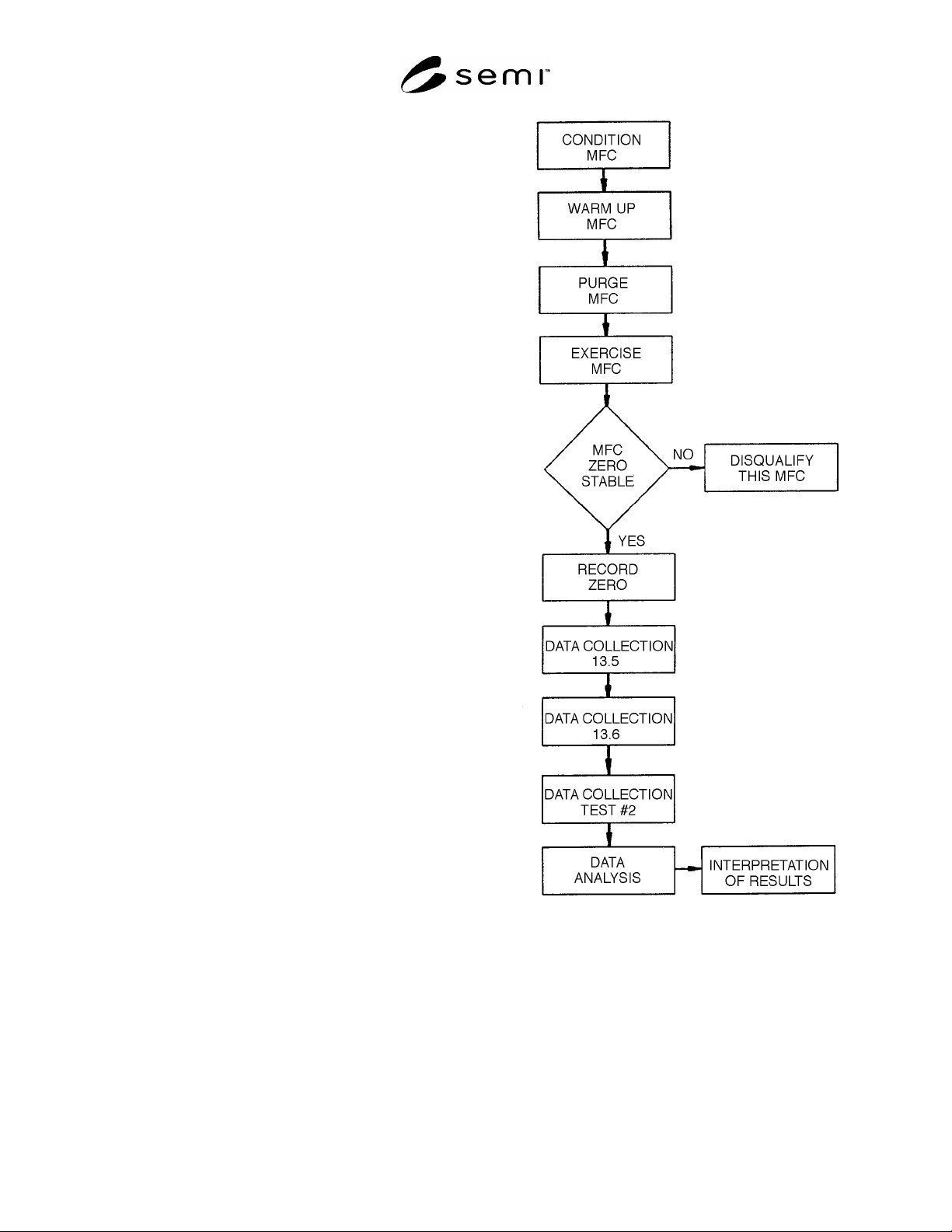
6.1 Specific procedures are given for characterizing
MFCs discharging to atmospheric pressure or into a
vacuum using accepted reference standards to
determine accuracy, linearity, repeatability, short-term
reproducibility, hysteresis, and deadband (see Figure 2).
Figure 2
Test Flowchart
7 Interferences
7.1 The accuracy rating of the measuring equipment
must include superior measurement capability
compared with that of the DUT. In no instance should
the accuracy rating of the measuring equipment be less
than twice that of the DUT (e.g., if the accuracy of the
DUT is ± 1 sccm, then the accuracy of the measuring