semi合集-English.pdf - 第5145页
SEMI M31-0705 © SEMI 1998, 2005 5 are turned more than 45° toward the position that unlocks the au tomated door from the box, the latch key holes on the door must be such that th e door i s not removable from the latch k…
SEMI M31-0705 © SEMI 1998, 2005 4
5.3 Inner and Outer Radii — All required concave features may have a radius of up to r65 to allow cleaning and to
prevent contaminant build-up. All required convex features may also have a radius of up to r66 to prevent small
contact patches with large stresses that might cause wear and particles. Note that these limits on the radius of all
required features are specified as a maximum (not a minimum) to ensure that the required features are not rounded
off too much. The lower bound on the radius is up to the FOSB supplier. Note also that this radius applies to every
required feature unless another radius is called out specifically. Here a required feature is an area on the surface of
the FOSB supplier. Note also that this radius applies to every required feature unless another radius is called out
specifically. Here a required feature is an area on the surface of the FOSB specified by a dimension (or intersections
of dimensions) that has a tolerance and not just a maximum or minimum (such as the edges of the robotic handling
flange).
5.4 Door — It is recommended that the FOSB not be vertical when it is opened or closed. When the FOSB is in a
vertical orientation with the door removed, the wafers must be restrained from touching each other by appropriate
wafer support design or other retaining techniques.
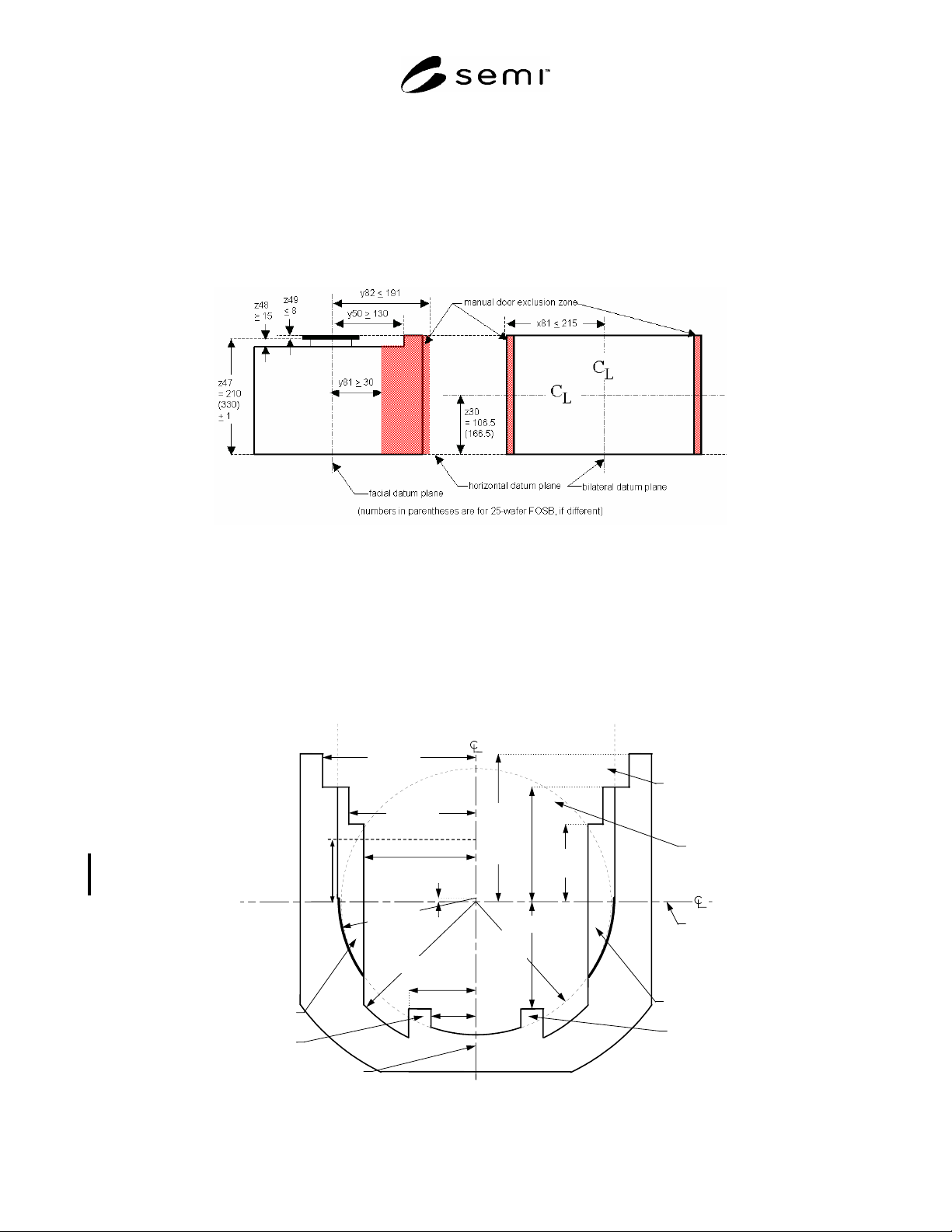
5.4.1 Manual Door — If chosen, the manual door option requires no automation to open the door. An exclusion
zone surrounding the manual door area is specified in the standard. There are several possible techniques for sealing
and clamping the manual door that meet user requirements. Therefore, only an exclusion zone surrounding the
manual door area is specified in this standard. All features of the door and door retaining mechanism must lie within
the exclusion zone illustrated in Figure 1 and must not interfere with other specified features (including the
kinematic couplings). Figure 1 and dimensions x81, y50, y81, y82, z47, z48 and z49 define the manual door area and
therefore apply only to the manual door option as described in this section. The y81 dimension applies from the
horizontal datum plane to the top surfaces of the FOSB (z47-z48 or z47+z49 at the upper door frame volume
specified by y50).
5.4.2 Automated-shippable Door — If chosen, the automated-shippable door must be designed to mate with a port
that conforms to SEMI E62. However, following characteristics of automate-shippable door must be considered.
5.4.2.1 Wafer Retaining Structure — The slot is usually designed that wafers are suspended in the slot without
contacting the surface of the slot for preventing the damage during transportation when FOSB door is closed. It
should be noted that wafer position of FOSB is different from that of FOUP when the door is closed due to the wafer
retaining structure.
5.4.2.2 Rear of Door (y51) — For manual door, FOSB has a y51
50 mm to hold wafers in large area at front
wafer retainer for keeping wafer quality during transportation. For automated-shippable door, FOSB has a
y51 140 mm to comply with SEMI E47.1.
5.4.2.3 Force between Box Door and Box (f34: defined by SEMI E62) — f34 is related to wafer retaining force
though, need to consider door is pulled by latching too. Even though, f34 is increased, minimum force applied to
wafer would be recommended for eliminating damage to the wafers in dynamic motion for opening and closing the
door.
5.4.2.4 Latch Key Torque (f30: defined by SEMI E62) — The required latch key torque depends on the closing
force.
5.4.2.5 A FOSB with an automated-shippable door should be able to withstand a force when applied to one of the
retaining features of up to 40N (f61) in any direction without negative impact to the intended function of the FOSB
(e.g. shell deformation, wafer positions, door closing capabilities).
5.5 Seal Zones for Door — In the Front Opening Shipping Box Automated Door Option the automated box door is
on the front side of the box (corresponding to the front side of the carrier where wafers are accessed so the door is
perpendicular to the wafers and parallel to the facial datum plane). The automated door and the carrier frame must
have surfaces that mate with the seal zones defined in SEMI E62. Specifically, the FOSB automated box door
option and the carrier frame must have surfaces that made with the seal zones and the reserved spaces for vacuum
application (which includes all of the circles bounded by r38 except for the holes for the registrations at the center of
each circle) defined in §5 of SEMI E62 (which specifies r38 as well as the seal zone dimensions). These automated
door and frame surfaces must be a distance of y52 from the facial datum plane and must have a flatness of y42. No
surface on the automated door may project further from the facial datum plane than the door seal zone and the
reserved spaces for vacuum application. The automated door must also be designed so that when the box is pressed
against the FIMS port, both latch keys on the port are inserted to their full length. Furthermore, when the latch keys
SEMI M31-0705 © SEMI 1998, 2005 5
are turned more than 45° toward the position that unlocks the automated door from the box, the latch key holes on
the door must be such that the door is not removable from the latch keys. There are no door seal zone requirements
for the manual door option, but a FOSB with the manual door must contain a frame seal zone that meets the frame
seal zone requirements specified in this section.
5.6 Wafer Retaining — When the FOSB is closed, the wafers must be retained in the FOSB to prevent movement
during subsequent handling, including shipping. It should be noted that wafers are typically shipped in a vertical
orientation and generally require support from a secondary package. It is recommended that this secondary package
be designed to allow for easy removal of the FOSB from the secondary package.
Figure 1
Manual Door Area
5.7 Wafer Orientation and Numbering — The wafers must be horizontal when the FOSB is placed on the coupling,
and the wafers slots are numbered in increasing order from bottom to top (so the bottom wafer is wafer number 1,
the next wafer up is wafer number 2, etc.).
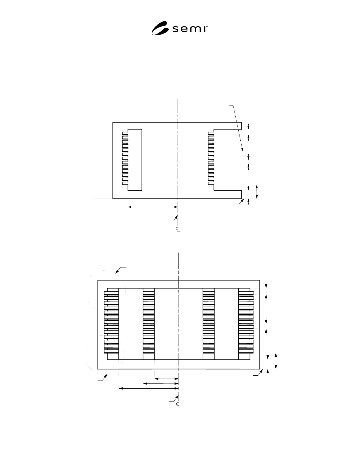
5.8 Internal Horizontal Dimensions — Figure 2 shows a cross-section of the horizontal boundaries of the FOSB
side domains (which contain the parts of the FOSB higher than z6 above the horizontal datum plane and lower than
z15 above the top wafer). In this and following figures, the most heavy lines are used for surfaces that have
tolerances (not surfaces that have only maximum or minimum dimensions).
y 5
120
y
52
165.5 ±
0.5 mm
(6.52 ±
0.02 in.)
y 49
134
y 11
85
x
52
170
facial
datum
p
lane
x
51
140
x
3
125
x
1
50
x
2
75
bilateral
datum
p
lane
r 4
170
ri
g
ht rea
r
side domain
left rea
r
side domain
front side of the FOSB where wafers are accessed
left front
side domain
wafer
p
ick-u
p
area
ri
g
ht front
side domain
r 1
151
r 2 =152
r 3
r 2 + 1
wafer set-
down and
extraction
volumes
y
1
3
+1
–
0
y51
50(manual door)
140(automated
door)
Figure 2
Top View of FOSB Internal Dimensions
SEMI M31-0705 © SEMI 1998, 2005 6
5.9 Internal Vertical Dimensions — Figures 3 through 7 show the vertical dimensions of the internal FOSB. Note
that z8 (the height of the bottom nominal wafer seating plane above the horizontal datum plane) and z12 (the
distance between adjacent nominal wafer seating planes) are given as absolute distances with no tolerance. This
means that the sum of actual height variations in the FOSB from the kinematic coupling to the supporting features
holding each wafer must be contained within the tolerance of z10 with no further stack-up at each higher wafer. The
method for meeting this requirement is left up to the FOSB supplier. Table 2 defines all dimensions for Figures 3
through 7.
Figure 3
Side View of FOSB Internal Dimensions
Figure 4
Front View of FOSB Internal Dimensions
horizontal
datum
plane
z
8
= 44
z
15
13
z
6
32
z
12
= 10
y
5
120
facial datum plane
front side of the FOSB where wafers
are accessed
detail in
Figure 8
detail in
Figure 6
horizontal datum plane
z
8
= 44
z
15
13
z
6
32
x
1
50
x2
75
x3
125
z
12
= 10
bilateral datum plane