semi合集-English.pdf - 第6859页
SEMI S2-0703a E © SEMI 1991, 2004 88 Figure R14-6 Fail-To-Safe Equipment Control Sy stem with Combined Netwo rk for Standard and Fail-To-Safe Communication and Separated Controller
SEMI S2-0703a
E
© SEMI 1991, 2004 87
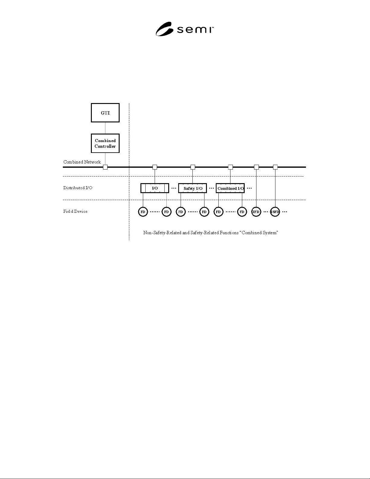
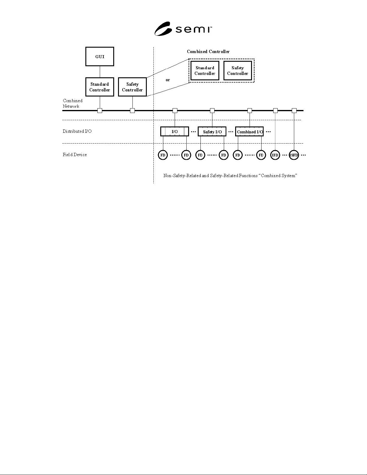
R14-8.3.2 Fail-to-safe Equipment Control System With Combined Network For Standard And Fail-to-safe
Communication — In Figures R14-5 and R14-6 the standard network and safety network have been combined into
one physical network. The standard controller and the safety controller can physically be consolidated into one
single unit. A combined network system is composed of technology that allows the non-safety-related and safety-
related communication to function on the same bus cable. Standard I/O, safety I/O and combined standard/safety
I/O can all connect to the network.
Figure R14-5
Fail-To-Safe Equipment Control System with Combined Network for Standard and Fail-To-Safe
Communication and Combined Controller
SEMI S2-0703a
E
© SEMI 1991, 2004 88
Figure R14-6
Fail-To-Safe Equipment Control System with Combined Network for Standard and Fail-To-Safe
Communication and Separated Controller
SEMI S2-0703a
E
© SEMI 1991, 2004 89
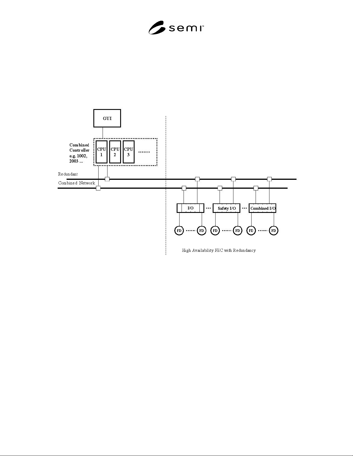
R14-8.3.3 Fault Tolerant Equipment Control System With High Availability And Redundant Network — In Figures
R14-2 through R14-6, the FECS enters a safe-state condition if a failure should occur; however, the production
process would be interrupted. In order to increase the availability of the automation system and therefore avoid
process downtime resulting from control system faults as well as faults and errors of components such as the power
supply, the industrial controller, the network connection, and the I/O modules need to be made redundant. Possible
architectures (see Figure R14-7) for achieving high availability include 2 oo 2, 2 oo 3, 2 oo 4, etc. (see R14-Section
9). Using fail-to-safe and high availability systems, injury to people or environmental damage can be prevented and
the production process can be continued without interruption.
Figure R14-7
Fault-Tolerant Equipment Control System with High Availability FECS and Redundant Network
R14-9 Guide to Assessment and Test Methods
R14-9.1 Assessment and testing of an electronic system (especially programmable systems) for safety integrity
levels (SIL) according to IEC 61508/ANSI/ISA-84.01 or risk categories according to ISO 13849-1 (EN 954-1) is a
complex and time consuming task, requiring a considerable level of knowledge and expertise. The use of
components such as safety PLCs and safety networks, that are certified by third parties for use in systems, and
include specific SILs and risk categories, simplifies the process of assessing the whole system.
NOTE 9: Certified (or listed) components need to be certified for functional safety use in safety critical systems. The final
integrated system should be fully assessed; using tools such as IEC 61508/ANSI/ISA-84.01 or ISO 13849-1 (EN954-1).
Assessments can often simplified by using combinations of certified components or FECS.
R14-9.2 Commissioning and Site Approval — Commissioning and site approval as described in IEC 61508 may be
confusing and therefore the following criteria are necessary for understanding:
R14-9.2.1 Safety-related components should meet the safety requirements defined during the risk analysis.
NOTE 10: Use of Notified Bodies, ATLs or a Professional Engineer to perform system assessment, type approval/site
approval/commissioning of electronic components and for machinery with industrial controllers is defined by the jurisdiction of
use.
R14-9.2.2 During control system commissioning, all relevant documentation of the pre-inspection should be
available. A pre-inspection usually is the first phase of a control system commissioning.