semi合集-English.pdf - 第591页
SEMI E80-0299 (Reapproved 1104) TEST METHOD FOR DETERMINING ATTITUDE SENSITIVITY OF MASS FLOW CONTROLLERS (MOUNTING POSITION) This test method was technically approved b y the Global Gases Comm ittee and is the direct re…
SEMI E79-0304 © SEMI 1999, 2004 24
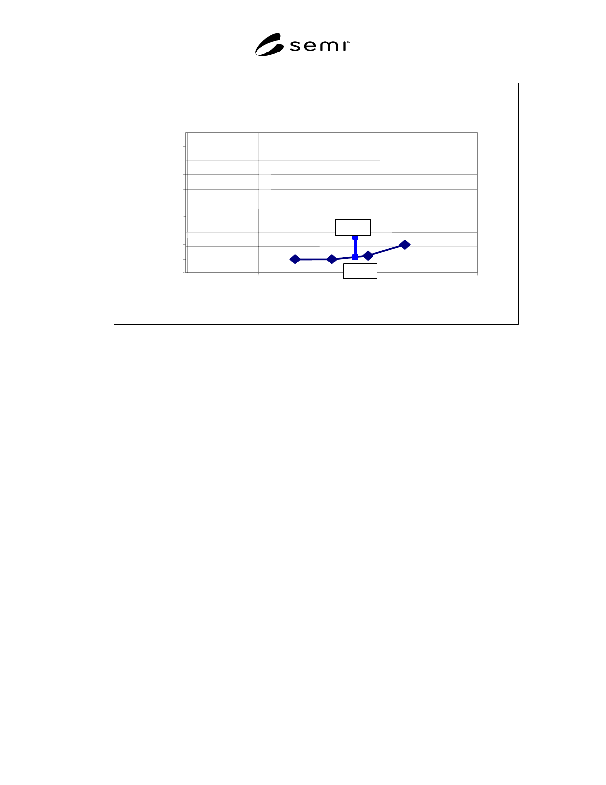
Figure R2-1
Productivity Efficiency Plane
NOTICE: SEMI makes no warranties or
representations as to the suitability of the standard set
forth herein for any particular application. The
determination of the suitability of the standard is solely
the responsibility of the user. Users are cautioned to
refer to manufacturer’s instructions, product labels,
product data sheets, and other relevant literature
respecting any materials mentioned herein. These
standards are subject to change without notice.
The user’s attention is called to the possibility that
compliance with this standard may require use of copy-
righted material or of an invention covered by patent
rights. By publication of this standard, SEMI takes no
position respecting the validity of any patent rights or
copyrights asserted in connection with any item
mentioned in this standard. Users of this standard are
expressly advised that determination of any such patent
rights or copyrights, and the risk of infringement of
such rights, are entirely their own responsibility.
Productivity Efficiency Plane [PEP]
0%
10%
20%
30%
40%
50%
60%
70%
80%
90%
100%
010203040
Effective Unit Throughput (uph)
IEE
and
OEE
(%)
OEE
IEE
Copyright by SEMI® (Semiconductor Equipment and Materials
International), 3081 Zanker Road, San Jose, CA 95134. Reproduction o
f
the contents in whole or in part is forbidden without express written
consent of SEMI.

SEMI E80-0299 (Reapproved 1104)
TEST METHOD FOR DETERMINING ATTITUDE SENSITIVITY OF MASS
FLOW CONTROLLERS (MOUNTING POSITION)
This test method was technically approved by the Global Gases Committee and is the direct responsibility of
the North American Gases Committee. Current edition approved by the North American Regional Standards
Committee on July 11, 2004. Initially available at www.semi.org September 2004; to be published
November 2004. Originally published in 1999; last published November 2004.
1 Purpose
1.1 The purpose of this test method is to provide a
standardized method for quantifying the effect of
mounting attitude on an MFC.
1.2 This document provides a common basis for
communication between manufacturers and users
regarding testing and describing MFC mounting effects.
2 Scope
2.1 This procedure describes a method to determine the
effect of attitude (mounting position) of a Mass Flow
Controller on flow span and zero.
2.2 The intent of this document is not to suggest any
specific testing program but to specify the test method
to be used when testing for parameters covered by this
method. Reference operating conditions represent the
environmental conditions where the "best" performance
can be expected.
2.3 The minimum test described in this document is to
test one MFC in 5 common mounting positions using
Nitrogen gas at 135.8 kPa (19.7 psia) and 308 kPa (44.7
psia). This test method can be used to evaluate
additional gases, pressures or mounting attitudes.
NOTICE: This standard does not purport to address
safety issues, if any, associated with its use. It is the
responsibility of the users of this standard to establish
appropriate safety and health practices and determine
the applicability of regulatory or other limitations prior
to use.
3 Limitations
3.1 It is not practical to evaluate performance under all
possible combinations of operating conditions. This test
procedure should be applied under laboratory
(reference) conditions; its intent is to collect sufficient
data to form a judgment of the field performance of the
MFC being tested.
3.2 The results from this test represent the performance
of the specific device tested i.e., make, model, full scale
flow and operating conditions. The results may not
apply to devices of different manufacture, model, full
scale flow or under different operating conditions.
3.3 Due to manufacturing variability, attitude
sensitivity may vary for the same model of MFC. To
statistically quantify attitude sensitivity for a particular
model of MFC, multiple samples should be tested.
4 Referenced Standards
None.
5 Terminology
5.1 Acronyms and Abbreviations
5.1.1 % F.S. — Percent Full Scale
5.1.2 DUT — Device Under Test
5.1.3 HBD — Horizontal Base Down. Mounting attitude
1, as shown in Figure 1.
5.1.4 HED — Horizontal Either side Down. Mounting
attitude 3, as shown in Figure 1.
5.1.5 HUD — Horizontal Upside Down. Mounting
attitude 5, as shown in Figure 1.
5.1.6 kPa — KiloPascal
5.1.7 MFC — Mass Flow Controller
5.1.8 psia
Pounds per Square Inch Absolute
5.1.9 SAS
max
the maximum Span Attitude
Sensitivity between two attitudes
5.1.10 SAS
nm
Span Attitude Sensitivity between
attitudes n and m
5.1.11 Sccm — Standard cubic centimeters per minute
5.1.12 Slm — Standard liters per minute
5.1.13 VFD — Vertical Flow Down. Mounting attitude
2, as shown in Figure 1.
5.1.14 VFU — Vertical Flow Up. Mounting attitude 4,
as shown in Figure 1.
5.1.15 VID — Vertical Inlet Down. Mounting attitude 4,
as shown in Figure 1.
5.1.16 VIU — Vertical Inlet Up. Mounting attitude 2, as
shown in Figure 1.
SEMI E80-0299 © SEMI 1999, 2004 1

5.1.17 ZAS
max
the maximum Zero Attitude Sensitivity
between two attitudes.
5.1.18 ZAS
nm
Zero Attitude Sensitivity between
attitudes n and m.
5.2 Definitions
5.2.1 actual flow — the flow rate as determined by the
flow standard used in the test procedure.
5.2.2 attitude — the mounting position of the MFC
with respect to the surface of the earth, as shown in
Figure 1.
5.2.3 indicated flow — the flow rate as determined by
the output of the DUT.
5.2.4 measured value — the actual flow through a
DUT, expressed in sccm or slm.
5.2.5 nameplate gas — the gas intended to be
controlled by the MFC in operation.
5.2.6 setpoint — the input signal provided to achieve a
desired flow, reported as sccm, slm, or percent full
scale.
5.2.7 span — the full scale range of the DUT.
5.2.8 zero drift — the undesired change in electrical
output (i.e., indicated flow), at a no-flow condition,
over a specified time period, reported in sccm or slm.
5.2.9 zero offset — the deviation from zero at a “no-
flow” condition reported in sccm, slm, % F.S. or mV.
6 Summary of Test Method
6.1 Gas flow, indicated flow and setpoint data are
collected for an MFC. This data is reduced to quantify
the relationship between the flow control by the MFC
and its relationship to the attitude of the MFC.
6.2 This method allows the user to determine the effect
of different mounting attitudes on MFC zero and span.
6.3 The standard test is determining the effect of
changing between attitudes 1 and 2 on Nitrogen. Other
typical MFC attitudes and gases may also be tested (see
Figure 1).
7 Interferences
7.1 The accuracy rating of the measuring equipment
shall be superior to that of the DUT. Preferably, the
measuring equipment will have an accuracy that is four
times better than the DUT. Calibration equipment must
have a valid calibration certificate.
7.2 Take care when using test instruments with a
specified accuracy expressed in percent of full scale.
7.3 Installation effects on the flow should be
minimized. Monitor pressure upstream of the DUT to
ensure that flow variations due to pressure are
minimized.
7.4 Verify electrical signals directly at the DUT
connector to ensure that the signals at the DUT and
standard agree with the signals at the data recording
equipment.
7.5 All electrical measurements should be read on
devices with at least 4.5 digits of resolution. These
devices must have valid calibration certifications.
7.6
All instrumentation in the test apparatus must
remain in a constant orientation except the device under
test.
8 Significance and Use
8.1 The data generated by this method is used to
estimate the effect-mounting attitude will have on the
performance of a mass flow controller. It would
typically be used to estimate the potential flow error
caused by using an MFC in attitude, other than the one
it was calibrated for.
9 Apparatus (see Figure 2)
9.1 Flow Standard A device or system that
accurately measures the flow and reports the actual
flow.
9.2 Data Acquisition System The system that
measures the electrical signals from the device under
test. The data acquisition system may also read the
signals from the flow standard, record test data and
control the test sequence.
9.3 Isolation Valves Valves that will positively shut
off the gas line.
9.4 Pressure Regulator
A device that regulates gas
pressure to a set value.
9.5 Pressure Transducer An instrument to measure
the gas pressure and report it as an electrical signal.
9.6 Flexible Gas Line Flexible tubing that will
allow the DUT to be moved to the various test attitudes
while the other components can remain in a fixed
position.
10 Materials
10.1 Clean, Dry N
2
, with 99.9% minimum purity.
10.2 MFC Calibration Test Gas as desired.
SEMI E80-0299 © SEMI 1999, 2004 2