semi合集-English.pdf - 第6888页
SEMI S5-0703 © SEMI 1993, 2003 3 P atm is standa rd atmospheric pressure 101 kPa absolute (14.7 psia) at sea level. P NT is the pressure in kPa gauge (psi g) from Table 1 that produces critical flow rate Q NT for a given…

SEMI S5-0703 © SEMI 1993, 2003 2
5 Terminology
5.1 Definitions
5.1.1 equivalent orifice — a passage that will allow
fluid flow equivalent to a round hole at 80% efficiency.
The efficiency, known as the orifice coefficient, will
typically vary from 65% (.65) for a sharp entrance to
95% (.95) for a well-rounded entrance. A flow rate
tolerance of ± 20% is used in Table 1 to allow for
variations in the entrance geometry and passage size.
Figure 1 illustrates the flow rate variation resulting
from this tolerance for different equivalent orifice sizes.
5.1.2 flow limiting device a device installed in a gas
cylinder valve that will reduce maximum flow from the
valve under full flow conditions.
5.1.3 flow rate flow rates in this guideline are given
in standard liters per minute (slm) at the standard
conditions of 0°C (32°F) and 101 kPa absolute (14.7
psia). This corresponds to the standard conditions used
for calibration of mass flow controllers used in
semiconductor processing systems.
5.1.4 hazardous gases gases that have a degree of
hazard rating in health, flammability, or reactivity of
class 3 or 4 in accordance with NFPA 704, or
equivalent rating by a regional standard.
5.1.5 mixing gas — an inert gas used to dilute another
gas.
6 Flow Limiting Device Criteria
6.1 Where Used Flow limiting devices should be
installed or incorporated into cylinder valves that are
used for gas cylinders containing the hazardous gases
listed in Table 2. Table 2 lists hazardous gases for
which devices are known to be feasible by reason of
testing and experience. SEMI encourages testing by its
members of hazardous gases not listed in Table 2 so
that new information can be added.
6.2 Materials The flow limiting device should be
made of materials that are compatible with the gas in
the cylinder.
6.3 Installation The flow limiting device should be
installed by the gas supplier or cylinder owner. See
Safety Warnings.
6.4 Identification The preferred method of
identifying flow limiting devices is by equivalent
orifice size as shown in Table 1. Other means of
identification, requiring identification by the supplier as
to the device installed, may be used if unambiguous.
6.5 Service Life Removable flow limiting devices
may be reused, but should be tested by the gas supplier
or cylinder owner before each use to assure that the
flow rate is as listed in Table 1.
6.6 Sizing A flow limiting device that will not allow
nitrogen flows out of the valve outlet to exceed the flow
rates listed for its equivalent orifice size in Table 1.
The flow limiting device should be the smallest size
that satisfies the process requirements. The user should
make the choice of flow rate based on safety
philosophy contained in SEMI S2.
NOTE 1: Flow rates determined by the calculations in this
safety guideline are based on critical flow where the cylinder
pressure is equal or greater than 2 atmospheres and pressure at
the outlet of the flow limiting device is 1 atmosphere.
Consult the flow limiting device supplier to determine the
minimum size that will provide the required process flow rate
when cylinder absolute pressure is less than 2 times outlet
absolute pressure.
7 Flow Rate Calculations
7.1 The flow rates in Table 1 are specified for critical
flow of nitrogen through the flow limiting device at
several cylinder pressure levels. Densities are given in
Table 2 for some hazardous gases. First determine the
critical flow of nitrogen through the flow limiting
device from Table 1, or calculate using the method
specified in Section 7.2. Then, using the method
specified in Section 7.3, calculate the gas and pressure-
corrected flow rates to determine the proper flow
limiting device size for the application. For gas
mixtures, the density can be calculated using the
method specified in Section 7.4.
7.2 Nitrogen Flow Rate— Nitrogen flow rate
correction for cylinder pressures not listed in Table 1
follows:
NOTE 2: This equation is only valid for ideal gases, and
critical flow that results for most gases when P
cyl
/P
atm
≥ 2.
It is necessary to multiply the equation by a compressibility
factor (Z) for better accuracy, however for nitrogen at
temperatures between -54 to +60°C (-65 to +140°F) and at
cylinder pressures less than 21,000 kPa gauge (3045 psig), the
result will be accurate within a few percent.
Q
N
= Q
NT
x
atmNT
atmcyl
PP
PP
+
+
Equation 1.
Q
N
is the critical flow rate in slm of nitrogen at
pressures not listed in Table 1.
Q
NT
is the critical flow rate in slm of nitrogen from
Table 1 that corresponds to a given equivalent orifice
size at pressure.
P
cyl is the gauge pressure kPa gauge (psig) in the gas
cylinder for which the flow rate is being calculated.

SEMI S5-0703 © SEMI 1993, 2003 3
P
atm is standard atmospheric pressure 101 kPa
absolute (14.7 psia) at sea level.
P
NT
is the pressure in kPa gauge (psig) from Table 1
that produces critical flow rate Q
NT
for a given
equivalent orifice size.
EXAMPLE 1: What is the minimum flow rate of
nitrogen through a 0.25 mm (0.01 inch) equivalent
orifice at 862 kPa gauge (125 psig)?
Q
N
= 2.90 ×
101700
101862
+
+
= 3.5 slm nitrogen (Q
NT
= 2.90 is
the minimum flow rate at 700 kPa gauge, the minimum
flow rate for a 0.25 mm orifice at any pressure listed in
Table 1 will provide the same result.)
EXAMPLE 2: What is the maximum flow rate of
nitrogen through a 0.25 mm (0.01 inch) equivalent
orifice at 12,414 kPa gauge (1,800 psig)?
Q
N
= 4.35 ×
101700
10112414
+
+
= 68 slm nitrogen (Q
NT
= 4.35
is the maximum flow rate at 700 kPa gauge.)
7.3 Hazardous Gas Flow Rate— Flow rate correction
for gases listed in Table 2 other than nitrogen follows:
NOTE 3: This formula is only valid for critical flow,
typically where P
cyl
/ P
atm
> 2
Q
g
= Q
N
×
g
DZ)(
25.1
Equation 2. (Use Q
NT
in place of
Q
N
when the applicable cylinder pressure is listed in
Table 2.)
Q
g
is the critical flow rate in slm of the gas listed in
Table 2.
D
g
is the standard density of the gas in kg/m
3
at one
atmosphere and 0°C (32°F) listed in Table 2.
Z is the compressibility factor at P
cyl
for the gas listed
in Table 2. For pressures not listed, interpolation of Z
with Z assumed proportional to pressure and equal to
1.0 at zero pressure should provide adequate accuracy
in the pressure and temperature ranges found in this
document. For gas mixtures with the mixing gas 95%
by volume or greater, use of Z for the mixing gas
should provide adequate accuracy, for lower
percentages consult the gas supplier.
NOTE 4: Density is the reciprocal of specific volume.
Density or specific volume is frequently given at a
temperature of 21.1°C (70°F). To convert 21.1°C (70°F) to
0°C (32°F) standard density, multiply by 1.077.
EXAMPLE 3: What is the minimum flow for Nitrogen
Trifluoride through a 0.75 mm (0.03 inch) equivalent
orifice at 700 kPa gauge?
Q = 26.1 ×
)20.3)(97.0(
25.1
= 16.6 slm Nitrogen
Trifluoride (Z is interpolated at 700 kPa)
7.4 Density For Gas Mixtures — Density correction
for mixtures of gases listed in Table 2, or Table 2 and
Table 3 follows:
D
mix
=
∑
V
g
× D
g
Equation 3. (For gas mixtures, use
D
mix
in place of D
g
in Equation 2.)
V
g
is the volume fraction of each gas in the mixture.
EXAMPLE 4: What is the density for a mixture of 5%
arsine and 95% nitrogen?
D
mix
= (.05 × 3.45) + (.95 × 1.25) = 1.36 kg/m
3
8 Related Documents
8.1 CGA Standard
2
CGA V-9 Compressed Gas Association Standard for
Compressed Gas Cylinder Valves
2 Compressed Gas Association, Inc., 1725 Jefferson Davis Highway,
Suite 1004, Arlington, VA 22202
SEMI S5-0703 © SEMI 1993, 2003 4
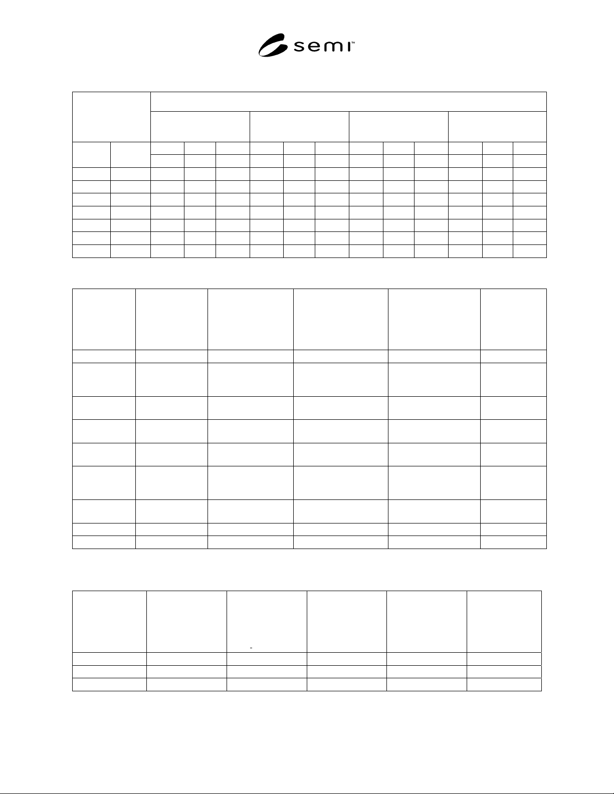
Table 1 Critical Nitrogen Flow Rates (Q
NT
) For Flow Limiting Devices
Critical Flow Rate (slm) of nitrogen at the following cylinder pressures:
Equivalent Orifice
Size
700 kPa gauge
(102 psig)
2100 kPa gauge
(305 psig)
7000 kPa gauge
(1015 psig)
21000 kPa gauge
(3045 psig)
min. nom. max. min. nom. max. min. nom. max. min. nom. max.
mm inch
−20% +20% −20% +20% −20% +20% −20% +20%
0.15 0.006
1.04
1.31
1.57 2.86
3.57
4.29 9.21
11.5
13.8 27.4
34.2
41.0
0.25 0.01
2.90
3.62
4.35 7.94
9.93
11.9 25.6
31.0
38.4 76.0
95.0
114
0.50 0.02
11.6
14.5
17.4 31.8
39.7
47.7 102
128
153 304
380
456
0.75 0.03
26.1
32.6
39.1 71.5
89.4
107 230
288
345 684
855
1026
1.00 0.04
46.4
58.0
69.6 127
159
191 409
512
614 1216
1520
1824
1.25 0.05
72.5
90.6
108 199
248
298 640
799
959 1900
2375
2850
1.50 0.06
104
130
157 286
357
429 921
1151
1381 2736
3421
4105
Table 2 Hazardous Gases for Which Flow Limiting Devices May be Used
Hazardous
Gas Type
Standard
Density (D), 1
atm., 0°C
[kg/m
3
(lbs/ft
3
)]
Cylinder Pressure
(P
cyl
) Typical Max.
@ Room Temp.
[kPa_gauge (psig)]
(See Note 1.)
Compressibility
Factor (Z) @ Typ.
Max.Cylinder
Pressure (See Note 2.)
Compressibility
Factor (z) @ 10%
Typ. Max.Cylinder
Pressure (See Note 2.)
Max. Flow
Rate (q) 0.25
mm (0.01 in.)
Equiv.Orifice
(slm)
Arsine, AsH3 3.45 (0.216) 1,410 (205) 0.81 0.98 5.5
Carbon
Monoxide,
CO
1.250 (0.078) 11,385 (1,650) 0.97 1.0 63
Diborane,
B2H6
1.250 (0.078) 1% in N2 12,410
(1,800)
0.29 @ 7,000 (1,015) 0.93 @ 700 (103) 1% in N2 68
Germane,
GeH4
3.415 (0.213) 607 (88) 0.94 0.99 2.4
Hydrogen,
H2
.090 (0.0056) 15,180 (2,200) 1.03 1.0 303
Nitrogen
Trifluoride,
NF3
3.200 (0.199) 10,000 (1,450) 0.64 0.96 43
Phosphine,
PH3
1.519 (0.095) 4,095 (594) 0.52 0.95 29
Silane, SiH4 1.433 (0.090) 8,280 (1,200) 0.36 0.94 70
Stibine, SbH3 1.444 (0.090) --- --- --- ---
NOTE 1: Cylinder pressures will vary, consult gas supplier to verify the actual cylinder pressure.
NOTE 2: Compressibility factors are interpolated from available data, consult gas supplier for alternate pressures.
Table 3 Mixing Gases
Mixing Gas Type
Standard Density
(D), 1 atm., 0°C
[kg/m
3
(lbs/ft
3
)]
Cylinder
Pressure* (P
cyl
)
Typical Max. @
Room Temp
[kPa
gauge (psig)]
Compressibility
Factor (Z) @ Typ.
Max. Cylinder
Pressure
Compressibility
Factor (Z) @ 10%
Typ. Max.Cylinder
Pressure
Max. Flow Rate
(Q) thru 0.25 mm
(0.01 in.)
Equivalent Orifice
(slm)
Argon, Ar 1.788 (0.111) 17,180 (2,490) 0.93 0.99 81
Helium, He 0.179 (0.011) 17,180 (2,490) 1.1 1.0 235
Nitrogen, N
2
1.250 (0.078) 17,180 (2,490) 1.0 1.0 93