semi合集-English.pdf - 第6253页
SEMI G49-93 © SEMI 198 9, 1996 1 SEMI G49-93 SPECIFICA TION FOR PLASTIC MOLDING PREFOR MS 1 Preface 1.1 Scope — T his specification de f i n es the physical requirem ents f or preform s made with therm osetting molding c…
SEMI G48-89 © SEMI 1989, 1996 9
Paragraph 5.22.1
Paragraph 5.17
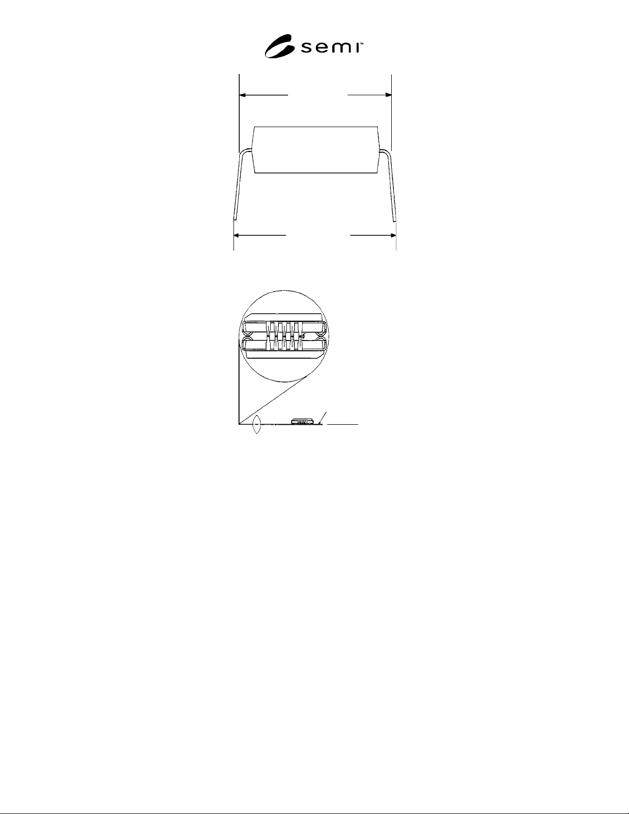
Figure 7A
Lens
Paragraph 5.15.2.2
{
Mirror
Light Source
Figure 8
NOTICE: These standards do not purport to address safety issues, if any, associated with their use. It is the
responsibility of the user of these standards to establish appropriate safety and health practices and determine the
applicability of regulatory limitations prior to use. SEMI makes no warranties or representations as to the suitability
of the standards set forth herein for any particular application. The determination of the suitability of the standard is
solely the responsibility of the user. Users are cautioned to refer to manufacturer’s instructions, product labels,
product data sheets, and other relevant literature respecting any materials mentioned herein. These standards are
subject to change without notice.
The user’s attention is called to the possibility that compliance with this standard may require use of copyrighted
material or of an invention covered by patent rights. By publication of this standard, SEMI takes no position
respecting the validity of any patent rights or copyrights asserted in connection with any item mentioned in this
standard. Users of this standard are expressly advised that determination of any such patent rights or copyrights, and
the risk of infringement of such rights, are entirely their own responsibility.
Copyright by SEMI® (Semiconductor Equipment and Materials
International), 3081 Zanker Road, San Jose, CA 95134. Reproduction o
f
the contents in whole or in part is forbidden without express written
consent of SEMI.
SEMI G49-93 © SEMI 1989, 19961
SEMI G49-93
SPECIFICATION FOR PLASTIC MOLDING PREFORMS
1 Preface
1.1 Scope — This specification de fines the physical
requirements for preforms made with thermosetting
molding compounds.
1.2 Significance — Consistent pre form quality
enhances moldability and finished product reliability.
1.3 Units — SI or American Custo mary units may be
used at the customers discretion. This specification uses
SI units.
2 Applicable Document
2.1 ASTM Specification
1
ASTM D 792 — Specific Gravity and Density of Plastic
3 Terminology
molding preform — Mold compound powder
compressed into a cylindrical shape and size with
specified diameter, weight, and density.
scoring — Marks, grooves, scratches, or notches with
definite length, width, and depth physical
characteristics.
side porosity — Voids or holes with visible shape, size,
and depth that are detected around a molding preform.
4 Ordering Information
Purchase orders for preforms furnished to this
specification shall include the following items:
Molding compound name/type
Preform diameter
Preform weight
5 Preform Specification
5.1 Appearance — The preform appearance,
considering such items as side porosity, scoring and
breakage shall be defined by agreement between
supplier and customer.
5.2 Preform Density as Percentage of Molded Density
5.2.1 Specification — The minimum values for
Preform Density as a Percentage of Molded Density for
preforms of various diameters are shown in Table 1.
1 American Society for Testing and Materials, 100 Barr Harbor
Drive, West Conshohoken, PA 19428-2959
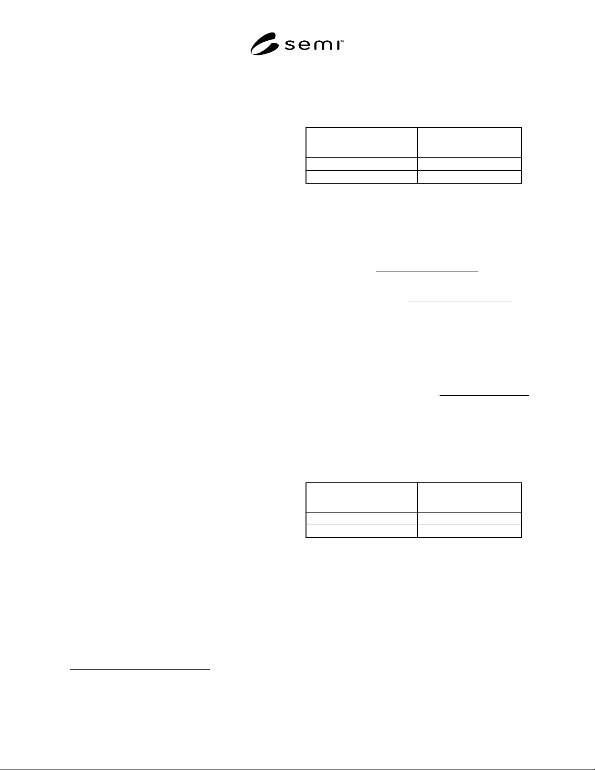
Table 1
Nominal Preform Diameter
(mm)
Percentage of Molded
Density (% Minimum)
< 16 87
> 16 85
5.2.2 Calculation
5.2.2.1 Preform Density — Measure w eight, height,
and diameter of preform.
Volume of approximately cylindrical preform (cm
3
) =
Height(cm) × π ×
4
m))Diameter(c Average(
2
Preform Density(g/cm
3
) =
)Preform(cm of Volume
Preform(g) ofWeight
3
5.2.2.2 Molded Part Density — Determine Molded
Part Density (g/cm
3
) per ASTM D 792.
5.2.2.3 Preform Density as Percentage of Model
Density.
Preform Density as Percentage
of Molded Density (%)
=
Preform Density
()
Molded Part Density
()
×100
5.3 Preform Diameter Tolerance — The tolerances on
preform diameters for variously sized preforms are
shown in Table 2.
Table 2
Nominal Preform Diameter
(mm) Tolerance (± mm)
< 16 0.30
> 16 1.25
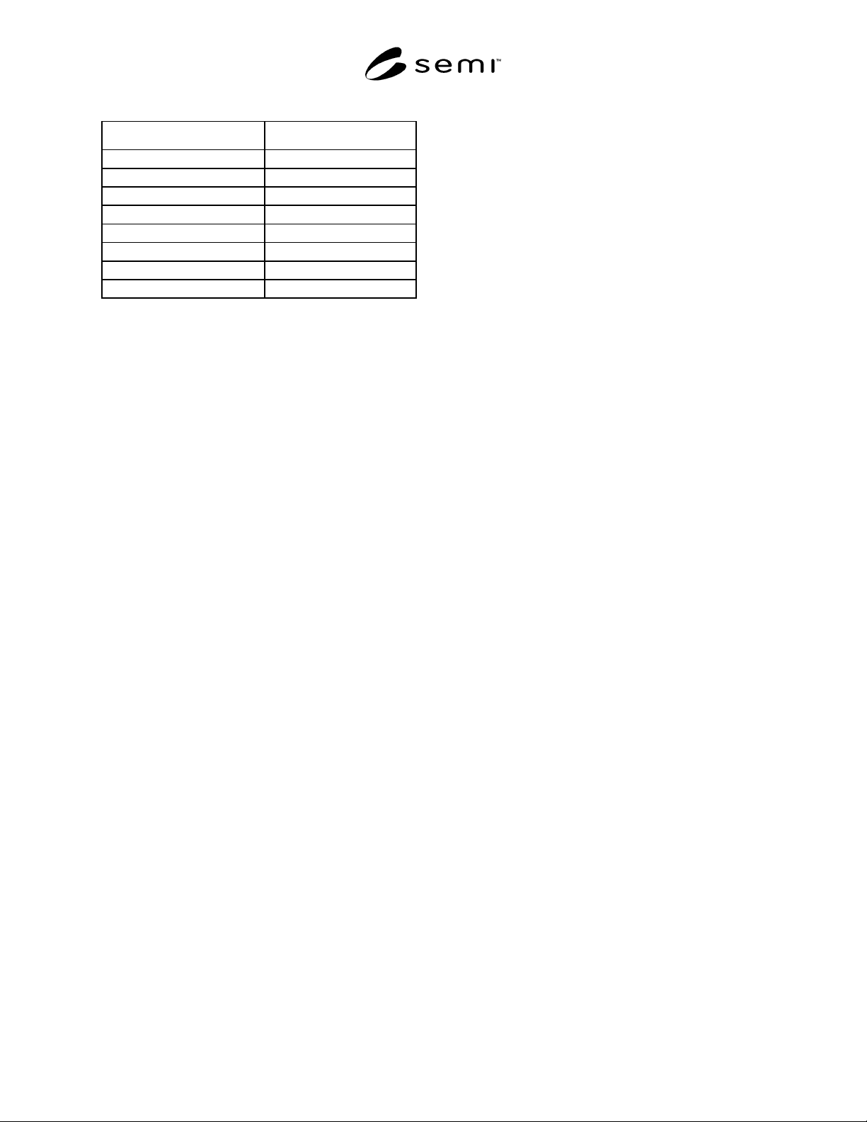
5.4 Preform Weight Tolerance — The weight
tolerances for variously sized preforms are shown in
Table 3.
SEMI G49-93 © SEMI 1989, 1996 2
Table 3
Preform Weight Range (g) Tolerance (± g)
1.8—4.0 0.15
> 4.0—8.0 0.20
> 8.0—< 15.0 0.25
15—< 16 0.50
16—40 1.00
> 40—80 2.00
> 80—150 3.00
> 150 4.00
NOTE 1: The handling characteristics of some molding
compounds may require tolerances different from those
shown above.
6 Sampling Plan
The sampling plan for inspecting preforms and the
molding parameters shall be agreed between supplier
and customer.
NOTE 2: Recommendation — It is suggested that a
minimum of three preforms be measured. On each
preform, height and diameter measurements, to the
nearest 0.0254 mm (0.001 inch). Preform weight
measurements should be taken to the nearest 0.1 gram.
NOTICE: These standards do not purport to address
safety issues, if any, associated with their use. It is the
responsibility of the user of these standards to establish
appropriate safety and health practices and determine
the applicability of regulatory limitations prior to use.
SEMI makes no warranties or representations as to the
suitability of the standards set forth herein for any
particular application. The determination of the
suitability of the standard is solely the responsibility of
the user. Users are cautioned to refer to manufacturer’s
instructions, product labels, product data sheets, and
other relevant literature respecting any materials
mentioned herein. These standards are subject to
change without notice.
The user’s attention is called to the possibility that
compliance with this standard may require use of
copyrighted material or of an invention covered by
patent rights. By publication of this standard, SEMI
takes no position respecting the validity of any patent
rights or copyrights asserted in connection with any
item mentioned in this standard. Users of this standard
are expressly advised that determination of any such
patent rights or copyrights, and the risk of infringement
of such rights, are entirely their own responsibility.
Copyright by SEMI® (Semiconductor Equipment and Materials
International), 3081 Zanker Road, San Jose, CA 95134. Reproduction o
f
the contents in whole or in part is forbidden without express written
consent of SEMI.