semi合集-English.pdf - 第197页
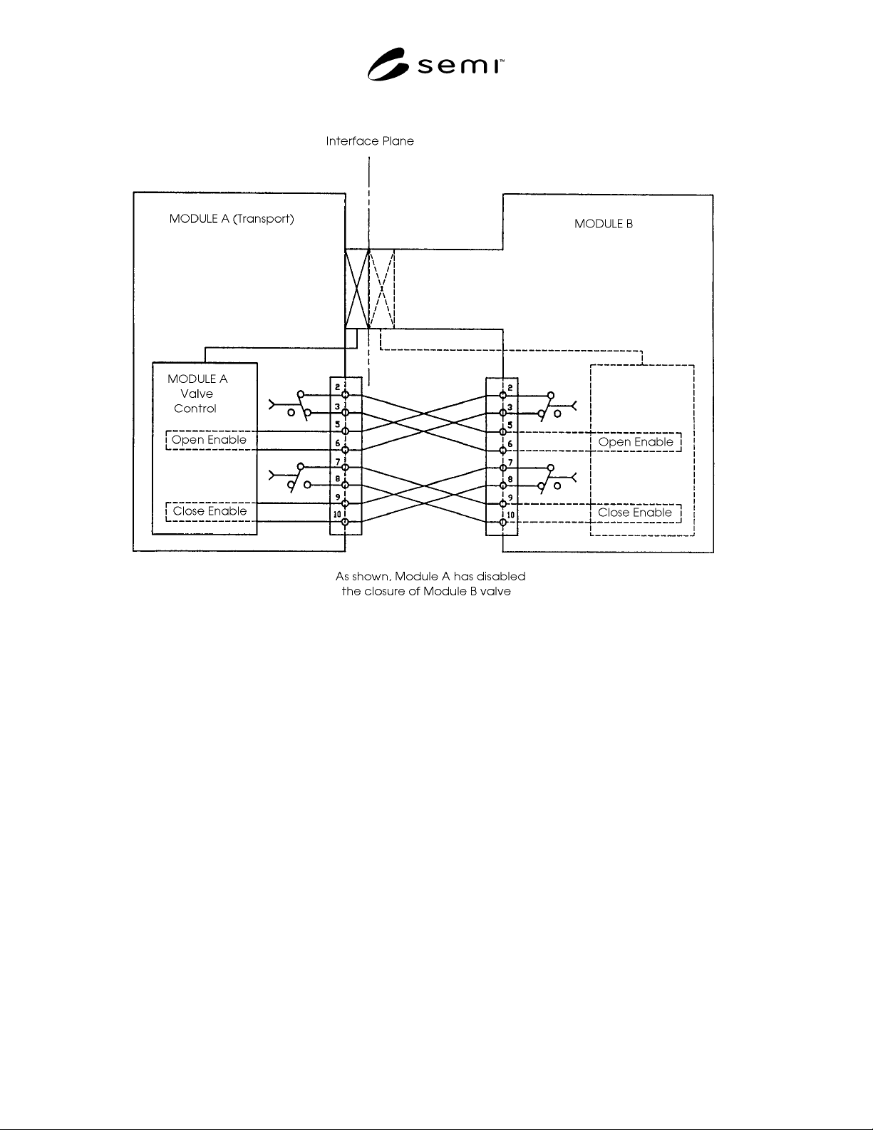
SEMI E24-92 © SEMI 1992, 2004 4 Figure R1-1 Illustration of Isolation Valve Interlock Standard NOTICE: The user’s attention is called to the possibility that compliance with this standard may require use of an inventi on…

SEMI E24-92 © SEMI 1992, 2004 3
RELATED INFORMATION 1
NOTICE: This related information is not an official part of SEMI E24 but was reapproved for publication by full
letter ballot procedures on February 28, 1999.
R1-1 Interlock Situations
R1-1.1 Examples are given below, for the different
types of modules, of situations in which it might be
considered hazardous for a connected module to
operate its isolation valve. Note that some of these
conditions prevent opening and others prevent closing
of the valves. (See Section 4.1.). Module types are
defined in SEMI E21. SEMI S2 provides guidance in
defining potential safety hazards. It is common practice
to detect valve positions and so verify operation, but
this is not an interface matter.
R1-1.2 Transport Module Examples — The transport
module end effector (see SEMI E22) is extended
beyond the interface plane. The connected module
should not close its isolation valve, as such an operation
could damage the end effector.
R1-1.2.1 The transport module is not at an acceptable
transfer pressure. Opening the isolation valve of the
connected module could result in damage to the valve
or wafer.
R1-1.3 Process Module Examples — The transport
module end effector exclusion volume (see SEMI E22)
is obstructed. The transport module should not open its
isolation valve and attempt to extend its end effector.
R1-1.3.1 The process module is not at an acceptable
transfer pressure. For instance, the module may be at
atmospheric pressure for preventive maintenance. The
transport module should not open its isolation valve.
R1-1.3.2 An unsafe partial pressure of a hazardous gas
exists in the process module. The transport module
should not attempt to open its isolation valve.
R1-1.4 Cassette Module Example — The cassette port
(loading door) is open, indicating the possibility of a
person' s hand in the cassette module. The transport
module should not operate its isolation valve to avoid
the possibility of injury to personnel.
R1-2 Illustration of Logic
R1-2.1 The interlock logic is illustrated in Figure A1
and described in Section 4.2. In the figure, the contacts
in module B are closed, enabling operation of the
isolation valve controlled by module A, while one of
the contacts in module A is open, preventing closure of
the isolation valve controlled by module B.
R1-3 Interlock Example
R1-3.1 This example elucidates some of the interlock
logic described in Section 4.2. In the case described
here, the Transport Module (TM) end effector is
extended into a Process Module (PM), which is
equipped with an isolation valve. This valve is inhibited
from closing by the interlock in the TM.
R1-3.2 A situation arises in the PM which results in its
interlock inhibiting the opening of the isolation valve
(which is already open) on the TM. As specified in
Section 4.3.3, the TM detects the interlock change and
immediately withdraws its end effector from the PM.
The TM interlock enables the closure of the PM
isolation valve (which the PM may do if that is the
appropriate response to the situation) and the TM can
close its isolation valve.
SEMI E24-92 © SEMI 1992, 2004 4
Figure R1-1
Illustration of Isolation Valve Interlock Standard
NOTICE: The user’s attention is called to the
possibility that compliance with this standard may
require use of an invention covered by patent rights. By
publication of this standard, Semiconductor Equipment
and Materials International (SEMI) takes no position
respecting the validity of any patent rights asserted in
connection with any item mentioned in this standard. In
particular, users of the specification should be aware
that Drytek, Inc., A Unit of General Signal, 16 Jonspin
Road, Wilmington, MA 01887-1087, Phone: (508) 657-
3933, has neither claimed nor disclaimed that
compliance with this specification would require use of
an invention covered by one or more of its patents.
Users of this standard are expressly advised that
determination of any such patent rights, and the risk of
the infringement of such rights, are entirely their own
responsibility.
These standards do not purport to address safety issues,
if any, associated with their use. It is the responsibility
of the user of these standards to establish appropriate
safety and health practices and determine the
applicability of regulatory limitations prior to use.
SEMI makes no warranties or representations as to the
suitability of the standards set forth herein for any
particular application. The determination of the
suitability of the standard is solely the responsibility of
the user. Users are cautioned to refer to manufacturer’s
instructions, product labels, product data sheets, and
other relevant literature respecting any materials
mentioned herein. These standards are subject to
change without notice.
Copyright by SEMI® (Semiconductor Equipment and Materials
International), 3081 Zanker Road, San Jose, CA 95134. Reproduction o
f
the contents in whole or in part is forbidden without express written
consent of SEMI.

SEMI E25-92 © SEMI 1992, 2004 1
SEMI E25-92 (Withdrawn 1104)
CLUSTER TOOL MODULE INTERFACE: MODULE ACCESS
GUIDELINE
This guideline was technically approved by the Global Physical Interfaces & Carriers Committee and is the
direct responsibility of the North American Physical Interfaces & Carriers Committee. Current edition
reapproved by the North American Regional Standards Committee on August 16, 2004. Initially available at
www.semi.org September 2004; to be published November 2004. Originally published in 1992; last
published June 1999.
Minor editorial changes were made to this document to conform to editorial guidelines.
NOTICE: This document was balloted and approved
for withdrawal in 2004.
1 Introduction
1.1 Scope — This guideline specifies an envelope
within which a cluster tool module is situated. Entry
and exit locations through the envelope and connection
locations to the module for utilities and facility services
are recommended.
1.2 Purpose — The purpose of the cluster tool module
access guideline is to provide assistance in the place-
ment of utilities and facility services to cluster tool
modules in order to improve access for maintenance
and service and to simplify cluster tool installation.
1.3 Impact — This guideline recommends that equip-
ment designs limit the placement of utility lines and
facility services to specific portions of the module
envelope.
1.4 Exceptions — Local safety regulations must always
take precedence over this guideline. Local conditions
may justify exceptions to this guideline.
NOTICE: This standard does not purport to address
safety issues, if any, associated with its use. It is the
responsibility of the user of this standard to establish
appropriate safety and health practices and determine
the applicability of regulatory or other limitations prior
to use.
2 Referenced Documents
2.1 SEMI Documents
SEMI E20 — Cluster Tool Module Interface: Electrical
Power and Emergency Off Standard
SEMI E21 — Cluster Tool Module Interface:
Mechanical Interface and Wafer Transport Standard
SEMI E24 — Cluster Tool Module Interface: Isolation
Valve Interlocks Standard
SEMI S2 — Safety Guidelines for Semiconductor
Manufacturing Equipment
NOTICE: Unless otherwise indicated, all documents
cited shall be the latest published versions.
3 Module Envelope
3.1 For the purpose of this guideline, the module enve-
lope is taken to be a set of six surfaces that completely
encloses a module. Individual module envelopes may
contact but not penetrate adjacent module envelopes.
The six surfaces are the inboard and outboard planes,
the two sides, the bottom and the top.
3.2 The inboard plane is the interface plane between a
transport module and any other module as defined in
SEMI E21; thus, a transport module possesses multiple
inboard planes. The outboard surface is parallel to the
interface plane and normally coincides with that part of
the module which is farthest from the interface plane.
Each side of the module envelope consists of several
vertical planes. The bottom surface generally coincides
with the floor, and the top is a horizontal plane that con-
tains the highest point of the module.
3.3 In the sections that follow, the distinction between
the physical module and the space reserved for the
module within the envelope must be kept in mind. Sec-
tion 4 refers to where utility lines penetrate the enve-
lope, and Section 5 refers to constraints on where these
lines connect to the physical module.
4 Allocation of Module Envelope Surfaces
4.1 The allocation of surfaces is subject to the need for
access to the interface plane, module movement, main-
tenance access space, and protection of module compo-
nents (particularly electrical components) from liquid
leaks.
4.2 Inboard Plane — To allow access to the isolation
valve(s), no utilities or facility services should be rout-
ed through the inboard surface close to the valve
boundary. ( See SEMI E21) The inboard surface is pre-
ferred for intra-tool communications, EMO (see SEMI
E20) and the interlock interface between the transport
module and the attached modules. (See SEMI E24.)