semi合集-English.pdf - 第6934页
SEMI S8-0705 © SEMI 1995, 2005 31 RELATED INFORMATION 2 WORKSTATION DESIGN NOTICE : This related i nformati on is not an official part of SEMI S8 and is not intended to m odify or supersede the official guideli nes. It w…
SEMI S8-0705 © SEMI 1995, 2005 30
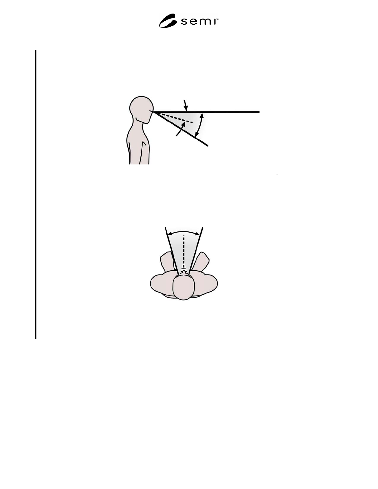
R1-4 Viewing Zones
R1-4.1 The Figures R1-3 and R1-4 depict the primary viewing areas for visual displays. This area is conical.
30
0
Primary
viewing
area
Eye at rest
15
0
Horizontal
line of sight
NOTE: This figure is based on data from: Pheasant, Stephen., Bodyspace: Anthropometry Ergonomics
and Design, Taylor and
Francis, 1996.
Figure R1-3
Side View of Primary Viewing Area for Visual Displays
Primary viewing area
30
0
NOTE: This figure is based on data from: Eastman Kodak Company, Ergonomic Design for People at Work (2
nd
Ed.), John
Wiley & Sons Inc., 2004.
Figure R1-4
Top View of Primary Viewing Area for Visual Displays

SEMI S8-0705 © SEMI 1995, 2005 31
RELATED INFORMATION 2
WORKSTATION DESIGN
NOTICE: This related information is not an official part of SEMI S8 and is not intended to modify or supersede the
official guidelines. It was derived from the work of the originating task force. Publication was authorized by full
ballot procedures. Determination of the suitability of the material is solely the user’s responsibility.
R2-1 General Considerations
R2-1.1 To enable good system performance, equipment and workspaces should be designed to accommodate the
physical dimensions of greater than 90 percent of user population. For recommended anthropometric data see
Related Information 1, Table R1-1, Figures R1-1 and R1-2.
R2-1.2 Where impairment of safety might result in danger to life, such as the inability to exit or escape under
emergency conditions, wider percentile ranges should be used (e.g., 1st through 99th percentile range).
R2-1.3 Many anthropometric databases cite unclothed dimensions.
R2-1.4 Critical and frequently used equipment, tools, and work items should be placed in the operator’s primary
viewing area.
R2-1.5 Provision for placement of required materials and informational items used during operation should be
accommodated in the design. Examples of materials/items include product boxes, wafer boxes, maintenance
manuals, and shop orders.
R2-2 Working Postures
R2-2.1 Workspace configurations that require static or frequent awkward postures (where the limbs or torso deviate
from a neutral position) should be avoided. For ranges of posture to avoid see Related Information 1.
R2-2.2 Equipment should be designed to avoid unsupported awkward static postures for operational tasks lasting
more than 20 seconds and unsupported awkward static postures for maintenance and service tasks lasting for more
than 40 seconds.
R2-2.3 Where applicable to tasks performed, equipment should be designed to allow both sitting and standing
operation.
R2-2.4 Controls, tools, and materials should be located so that the most frequent activities are performed from a
neutral posture.
R2-2.5 To prevent users from bending at the waist, the design should place users close to the point of operation by
providing adequate leg and foot clearance and keeping work materials at an appropriate height. See the “Supplier
Ergonomics Success Criteria” in Appendix 1 for design criteria.
R2-3 Standing Workstations
R2-3.1 See the “Supplier Ergonomics Success Criteria” in Appendix 1 for standing workstation design criteria.
R2-3.2 Display screens should be perpendicular to the normal line of sight and the angle of the screen should be
adjustable or positioned to minimize glare.
R2-4 Sitting Workstations
R2-4.1 See the “Supplier Ergonomics Success Criteria” in Appendix 1 for seated workstation design criteria.
R2-4.2 Sit/stand workstations are workstations where the operator can assume a standing posture or a seated posture
using a task stool.

SEMI S8-0705 © SEMI 1995, 2005 32
RELATED INFORMATION 3
DESIGN FOR MAINTAINABILITY AND SERVICEABILITY
NOTICE: This related information is not an official part of SEMI S8 and is not intended to modify or supersede the
official guidelines. It was derived from the work of the originating task force. Publication was authorized by full
ballot procedures. Determination of the suitability of the material is solely the user’s responsibility.
R3-1 General Considerations
R3-1.1 Equipment design should facilitate rapid and positive fault detection and isolation of defective items.
R3-1.2 Standard parts should be used whenever prac-ticable. Where practical, components should be replace-able
as modular packages and configured for rapid re-moval and replacement (e.g., use of a standard fastener throughout
a design).
R3-1.3 Equipment requiring periodic calibration and adjustment should be readily accessible without disassembly.
R3-1.4 Use of cleanroom gloves reduces maximum allowable grip forces listed in Related Information 1, Table R1-
3 by 15%.
R3-1.5 Use of cotton gloves reduces maximum allowable grip forces listed in Related Information 1, Table R1-3 by
26%.
R3-1.6 Use of chemical protective gloves reduces maximum allowable grip forces listed in Related Information 1,
Table R1-3 by 19%.
R3-1.7 Component design should preclude improper mounting and installation of any component.
R3-1.8 Guides, tracks, or stops should be provided as necessary to facilitate handling and prevent damage to
equipment or injury to personnel.
R3-1.9 Refer to ANSI/IES “Practice for Industrial Lighting” for recommended illumination based on task
characteristics.
R3-1.10 Structural members or permanently installed equipment should not visually or physically prevent
adjustment, servicing, removal of replaceable equipment, or other required maintenance tasks.
R3-1.11 Items which require rapid or frequent maintenance should be most accessible. Predicted or known high
failure-rate items should be accessible for replacement with minimal removal of nearby or adjacent non-failed items.
If it is necessary to remove non-failed items, then the total ergonomic impact must be assessed to determine
conformance.
R3-1.12 Sufficient space should be provided for the use of standard test equipment and required maintenance tools
without difficulty or hazard. Self-checking or built-in test features are recommended.
R3-2 Cables, Connectors, Plugs, Receptacles, and Circuit Boards
R3-2.1 Connectors which may need to be disconnected and reinstalled during the life of the tool that are mounted in
close proximity should have clearance so that each one can be easily removed and reinstalled.
R3-3 Equipment Enclosures
R3-3.1 Equipment enclosures should be easily removable or sufficiently larger than the item they cover to facilitate
installation and removal of components.
R3-3.2 Cover or shield holes should be large enough for fastener clearance without precise alignment.
R3-3.2.1 Access openings should be designed to permit unobstructed physical and visual operation. Size and shape
of the access should allow for easy passage of equipment and body parts of a 95th percentile North American male
with necessary PPE and tools, as appropriate.
R3-3.2.2 Unless prohibited from a microcontamination standpoint, access covers should be hinged or sliding. Lift
off covers will require manual material handling analysis.