semi合集-English.pdf - 第4244页
SEMI F77-0703 © SEMI 2003 3 7 Possible Interferences 7.1 Specimens must be exam ined after testing to confirm pitting. A possible interference is failure by crevice corrosion in which case the test is invalid . Crevice c…
SEMI F77-0703 © SEMI 2003 2
4.2 ASTM
1
Standards
ASTM G3 — Standard Practice for Conventions
Applicable to Electrochemical Measurements in
Corrosion Testing
ASTM G15 — Standard Terminology Relating to
Corrosion and Corrosion Testing
ASTM G150 — Test Method for Electrochemical
Critical Pitting Temperature Testing of Stainless Steels
NOTICE: Unless otherwise indicated, all documents
cited shall be the latest published versions.
5 Terminology
NOTE 1: Unless otherwise stated, the sign conventions used
in this test method are in agreement with ASTM G3, and the
terminology relating to corrosion and corrosion testing is as
defined in G15.
5.1 Definitions
5.1.1 CPT-Critical Pitting Temperature — the lowest
temperature at which stable propagating pitting occurs
on the test surface under the specified test conditions, as
indicated by a rapid increase beyond a specified limit of
the measured anodic current density of the test surface.
5.1.2 passive potential range — the potential range
over which the current density is independent of
potential. The current is a very low value due to
formation of an oxide layer.
5.1.3 pitting — corrosion of a metal surface, confined
to a point or small area, that takes the form of cavities.
5.1.4 pitting potential range — the range of measured
potentials where pitting is initiated. This potential
range only exists above the minimum CPT.
5.1.5 potential dependent CPT — the CPT determined
at a potential within the pitting potential range of the
tested surface.
5.1.6 potential independent CPT — the CPT
determined at a potential above the pitting potential
range, but below the transpassive potential range.
5.1.7 temperature ramp — the rate (° C/min) at which
the test temperature is increased during the test.
5.1.8 transpassive potential — the potential above the
passive potential range, in which the current density
increases rapidly as the potential increases.
5.1.9 wetted surface — surfaces of a component in
contact with the contained fluids.
1 Available from American Society for Testing and Materials, 100
Barr Harbor Drive, PO Box C700, West Conshohocken, PA 19428-
2959. Fax: 1-610-832-9555. Website: http://www.astm.org.
6 Summary of Method
6.1 The test method measures the critical pitting
temperature (CPT) by using a potentiostatic technique
and a temperature scan. Specific types of specimen
holders are used to minimize crevice corrosion, which
is another type of corrosion mechanism that can
complicate the CPT result. The test is performed in an
aqueous electrolyte solution, such as 1 M NaCl. After
polarizing the specimen to a potential above the pitting
potential, the temperature scan begins at 0°C. The
solution is heated at a constant rate of 1°C/minute while
the current is measured by means of a
potentiostat/galvanostat instrument. The CPT, as
defined in Section 5.1.1, is the temperature at which the
current density increases above 100 µ A/cm
2
for 60
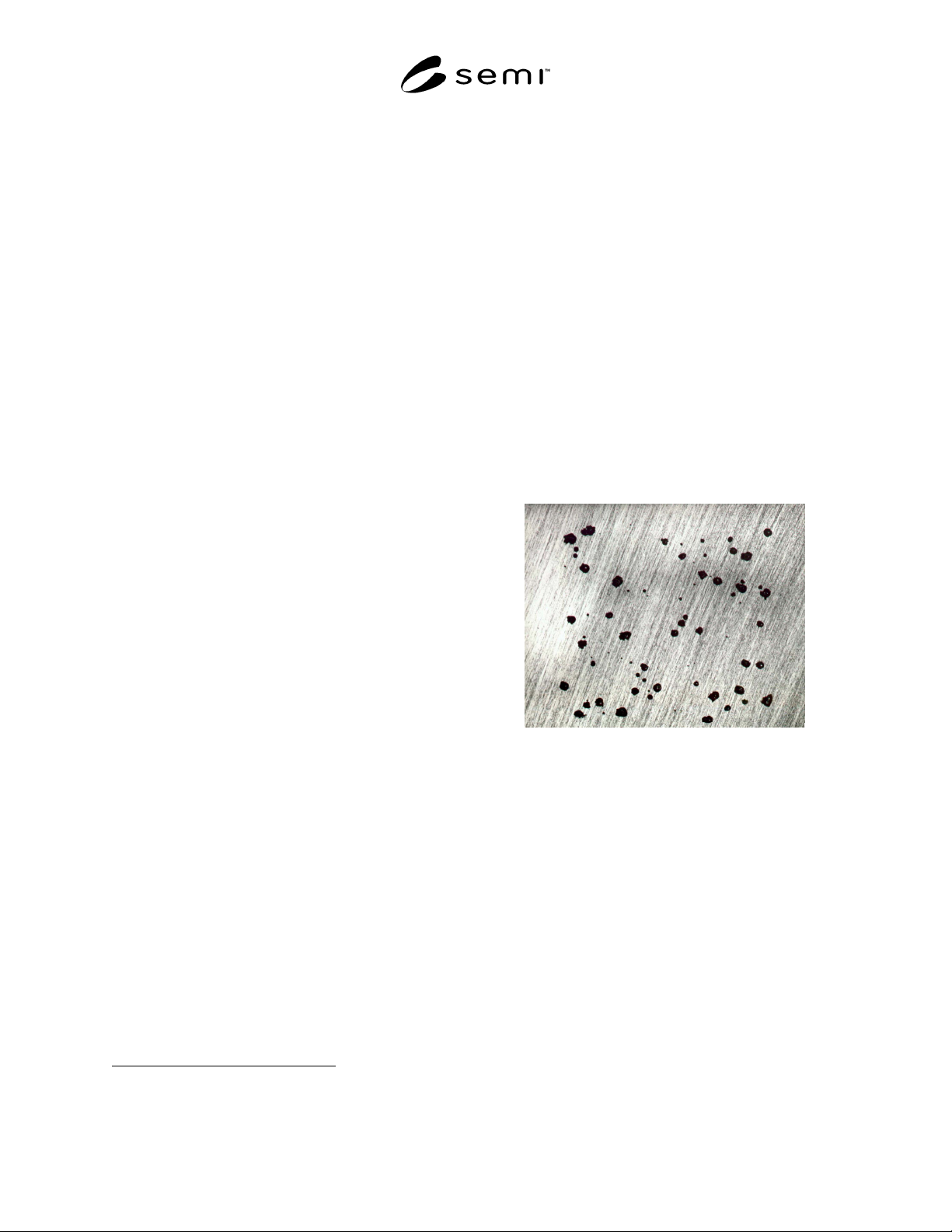
seconds. Pitting is normally confirmed by visual or
microscopic observation of the specimen after testing as
shown in Figure 1. Refer to Appendix X1 in ASTM
G150 for a description of the relationship between the
pitting potential and the critical pitting temperature.
Figure 1
Examples of Pitting on Type 316 Stainless Steel
After a Pitting Potential Test Performed at 25°C in 1
M NaCl (11 × Magnification)
(Ref 17.1)
SEMI F77-0703 © SEMI 2003 3
7 Possible Interferences
7.1 Specimens must be examined after testing to
confirm pitting. A possible interference is failure by
crevice corrosion in which case the test is invalid.
Crevice corrosion can occur at the seal of the specimen
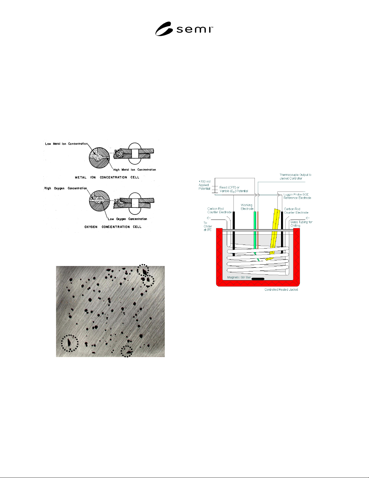
holder. Figure 2 shows the mechanism by which
crevice corrosion occurs, and Figure 3 gives an
example of the typical morphology of crevice corrosion
from a pitting potential test performed on type 316
stainless steel using masked edges. It should also be
noted that the critical crevice temperature (CCT) for
AISI 316L is less than 10°C.
Figure 2
Mechanism for Crevice Corrosion
(See Section 17.2.)
Figure 3
Examples of Crevice Corrosion (Dashed Circles) on
Type 316 Stainless Steel After a Pitting Potential
Test in 1 M NaCl at 35°C. 11 × Magnification (See
Section 17.1.)
8 Apparatus
8.1 In general, refer to ASTM G150 for a detailed
description of the apparatus and accessories necessary
to carry out the CPT evaluation. Specifically, Sections
6.1 to 6.9 of ASTM G150 describe the potentiostat, the
potential measuring instrument, the current measuring
instrument, the temperature controller, and the
temperature measurement instrumentation.
8.2 Flat Specimens — The test cell for flat specimens
(consisting of two options, G5-type cell and a flushed-
port cell), are given in Appendices X2 and X3 of
ASTM G150 with a detailed description of each.
8.3 Tubular Specimens — The test cell can be modified
for testing tubular specimens. The modified test cell
consists of a 2-L glass beaker cut to 4.5 in. high and
capped with a polyethylene cover. A three-electrode
set up is used consisting of the test specimen, an SCE
reference electrode inserted in a Luggin probe, and two
graphite rods as counter electrodes. See Figure 4 for the
modified test cell set-up.
Figure 4
Modified Test Cell for CPT Testing of Tubular
Specimens; Tubing Specimen is the Working
Electrode
9 Test Specimens
9.1 Flat Specimens — In general, refer to ASTM G150
for a detailed description of the flat specimen.
9.2 Tubing Specimens — Tubing specimens consist of
2.0-in. lengths of tubing. The tubing should be faced,
and the cut ends should be masked with a non-reactive
lacquer.
9.3 All specimens should be masked to isolate the test
to the surface of interest only. This can be
accomplished by masking with a non-reactive lacquer,
which can be baked to ensure optimum adhesion.

SEMI F77-0703 © SEMI 2003 4
Alternately, plater’s tape can also be used, leaving 0.25
in. uncovered at the end for electrical contact.
9.4 Finish — In general, refer to ASTM G150 for
details on the typical finish of the test specimens. Since
surface finish can effect the CPT results, surface
finished should be done as consistently as possible
within a sample set. Details of the surface finishing
process, parameters and characterization should be
provided in the test report as outlined in Section 15.
9.5 Sampling — It is recommended that a minimum of
3 specimens, and preferably 5 or more, should be used
to obtain statistical significance in the testing results.
9.6 Test Area — In general, refer to ASTM G150,
which states a minimum test area of 1 cm
2
. This
minimum test area is required for both flat specimens
and tubing specimens.
10 Reagents And Materials
10.1 In general, refer to Section 8 of ASTM G150
describing the purity of the reagents and water needed
for the test solution as well as the purity of the N
2
purging gas.
10.2 Standard Test Solution — Comparison of the CPT
results requires consistency in the test solution, so it is
recommended that a 1 M (mole/liter) sodium chloride
(NaCl) electrolyte be used as electrolyte. However,
because of the different processes gases used by the
semiconductor industry (HCl, HBr, Cl
2
, BCl
3
, HF,
WF
6
), it is possible to substitute another test solution to
represent the particular anion of the process gas which
may impart different pitting characteristics (e.g., 1 M
NaBr, or 1M NaF).
11 Applied Potential
11.1 Stainless Steel — In general, refer to section 9 of
ASTM G150, which provides the standard anodic
potential commonly used for most stainless steels (an
anodic potential of 700 mV versus SCE at 25°C).
Section 9 also provides an alternative potential if there
is uncertainty as to whether this potential is sufficiently
high to obtain a potential independent CPT.
11.2 Alternative Alloys — Alloys other than 316L
stainless steel can be tested using the applied potential
given in Section 11.1.
12 Procedure
12.1 In general refer to Section 10 of ASTM G150 for
details on specimen mounting, cleaning, and placement,
test solution preparation, test procedure, and completion
of the test.
12.2 Refer to Annexes A1 and A2 in ASTM G150 for
guidelines to calibrate the specimen temperature.
12.3 Tubing specimens — Tubing testing requires
different specimen mounting and preparation than given
in Section 9 of ASTM G150. Tubing specimens should
be placed vertically in solution so that approximately
one inch is submerged.
13 Visual Examination Of Test Specimen
13.1 In general, refer to Section 11 of ASTM G150 for
a description of the visual examination of the test
specimen.
14 Data Analysis
14.1 In general, refer to Section 12 of ASTM G150 for
details on evaluating the critical pitting temperature.
15 Reporting Results
15.1 Section 13 of ASTM G150 provides a list of
mandatory information required in the test report.
15.2 Other mandatory information that should be
provided are the starting test electrolyte composition,
the diameter of the tubing for tubing specimens,
identification of the surface finish process (e.g.,
electropolish, passivation), and any other specific
parameters or characterization related to the surface
finish process. Welded and non-welded specimens
should also be clearly identified, as well the welding
procedure used to weld the specimen.
16 Precision and Bias
16.1 The precision of this test method is yet to be
determined
16.2 The bias of this test method is yet to be
determined.
17 References
17.1 Blum, Michael. M.S. Thesis. University of
London, England, December 1970.
17.2 Philip A. Schweitzer, Ed. “Corrosion and
Corrosion Protection Handbook.” Marcel Dekker, New
York, p. 11, 1983.