semi合集-English.pdf - 第289页
SEMI E47.1-0305 © SEMI 1997, 2005 4 6.3 Interior Di mensions — The interior of t he FOUP must have the int erior dim ensions of the cassette specified in SEMI E1.9. Many of these dimensions are m easured from a horizonta…
SEMI E47.1-0305 © SEMI 1997, 2005 3
4.1.6 front-opening unified pod (FOUP) — a box (that complies with SEMI E47.1) with a non-removable cassette
(so that its interior complies with SEMI E1.9) and with a front-opening interface (that mates with a FIMS port that
complies with SEMI E62).
4.1.7 horizontal datum plane — a horizontal plane from which projects the kinematic-coupling pins on which the
carrier sits. On tool load ports, it is at the load height specified in SEMI E15 and might not be physically realized as
a surface (as defined in SEMI E57).
4.1.8 minienvironment — a localized environment created by an enclosure to isolate the product from contamination
and people.
4.1.9 nominal wafer center line — the line that is defined by the intersection of the two vertical datum planes (facial
and bilateral) and that passes through the nominal centers of the seated wafers (which must be horizontal when the
carrier is placed on the coupling) (as defined in SEMI E57).
4.1.10 pod — a box having a Standard Mechanical Interface (SMIF) per SEMI E19.
4.1.11 robotic handling flanges — horizontal projec-tions on the top of the FOUP for lifting and rotating the FOUP.
4.1.12 wafer carrier — any cassette, box, pod, or boat that contains wafers (as defined in SEMI E15).
5 Ordering Information
5.1 Intended Use — This standard is intended to specify 300 mm FOUPs over a reasonable lifetime of use, not just
those in new condition. For this reason, the purchaser needs to specify a time period and the number and type of uses
to which the FOUPs will be put. It is under these conditions that the FOUPs must remain in compliance with the
requirements listed in §6.
5.2 Temperature Ranges — The purchaser of 300 mm FOUPs needs to specify two sets of temperatures to which
the FOUPs might be exposed. An operating temperature range is the set of environmental temperatures in which the
FOUPs will remain in compliance with the requirements listed in §6. A temporary temperature range is the set of
environmental temperatures to which the FOUPs can be exposed such that when the FOUPs return to the operating
temperature range, the FOUPs will be in compliance with the requirements listed in §6. Limits on exposure times to
elevated temperatures should be specified. Also, the purchaser needs to specify a range of temperatures for the
wafers that might be inserted in the FOUPs.
5.3 Fire Resistance — The purchaser of 300 mm FOUPs may need to consider the flammability of the FOUPs.
5.4 Info Pad Configurations — The purchaser of 300 mm carriers needs to specify the desired info pad
configuration (up or down).
6 Requirements
6.1 Kinematic Couplings — The physical alignment mechanism from the FOUP to the tool load-port (or a nest on a
vehicle or in a stocker) consists of features (not specified in this standard) on the top entity that mate with three or
six pins underneath as defined in SEMI E57. Most of the dimensions of the FOUP are determined with respect to the
three orthogonal datum planes defined in that standard: the horizontal datum plane, the facial datum plane, and the
bilateral datum plane. All of the dimensions for the FOUP are bilaterally symmetric about both the bilateral and
facial datum planes with the following exceptions:
The features that mate with the kinematic coupling pins and the FOUP sensing pads are symmetrical only about
the bilateral datum plane.
The FOUP has a door only on the front and conveyor rails on the left and right sides that are required to extend
all the way to the front.
The orientation notches on the robotic handling flange are different for each of the four sides.
The three features that mate with the kinematic coupling pins must provide a lead-in capability that corrects a FOUP
misalignment of up to r69 in any horizontal direction.
6.2 (This section, “Internal Kinematic Couplings” is no longer applicable, and is intentionally left blank so as to
maintain paragraph numbering.)
SEMI E47.1-0305 © SEMI 1997, 2005 4
6.3 Interior Dimensions — The interior of the FOUP must have the interior dimensions of the cassette specified in
SEMI E1.9. Many of these dimensions are measured from a horizontal datum plane, so an internal horizontal datum
plane is still specified to be z44 above the horizontal datum plane under the FOUP.
6.4 Door
6.4.1 (This section (6.4.1) is no longer applicable, and is intentionally left blank so as to maintain paragraph
numbering.)
6.4.2 , The FOUP door is on the front side of the FOUP (corresponding to the front side of the cassette where
wafers are accessed so the door is perpendicular to the wafers and parallel to the facial datum plane), and the door
and its frame must be designed to mate with a port that conforms to SEMI E62. Specifically, the FOUP door and its
frame must have surfaces that mate with the seal zones and the reserved spaces for vacuum application (which
includes all of the circles bounded by r38 except for the holes for the registration pins at the center of each circle)
defined in ¶¶5.3 and 5.6 of SEMI E62 (which specifies r38). These FOUP door and frame surfaces must be a
distance of y52 from the facial datum plane and must have a flatness of y42. No surface on the FOUP door may
project further from the facial datum plane than the door seal zone and the reserved spaces for vacuum application.
The door of the FOUP must also be designed so that when the FOUP is pressed against the FIMS port, both latch
keys on the port are inserted to their full length. Furthermore, when the latch keys are turned more than 45° toward
the position that unlocks the FOUP door from the FOUP, the latch key holes on the door must be such that the door
is not removable from the latch keys.
6.5 Wafer Capture and Centering — When the FOUP is closed, the wafers must be captured in the FOUP to
prevent movement during transport. Wafer capture must include gently pushing the wafers to the rear of the cassette
to center them.
6.6 Internal Dimensions —The interior of any FOUP must not intrude on the end effector exclusion zone, and the
inside of the door must not intrude more that y51 toward the facial datum plane. The interior of the FOUP between
y11 and the door opening must not protrude higher than z6 above the internal horizontal datum plane and lower than
z15 above the top nominal wafer plane. Horizontally, it must not protrude closer to the bilateral datum plane than
x51 between y11 and y49 or closer than x52 between y49 and y52 (as shown in Figure 10). Dimensions x51, x52,
y49, and y52 are specified in Table 1, and y11, z6, and
z15 are specified in SEMI E1.9.
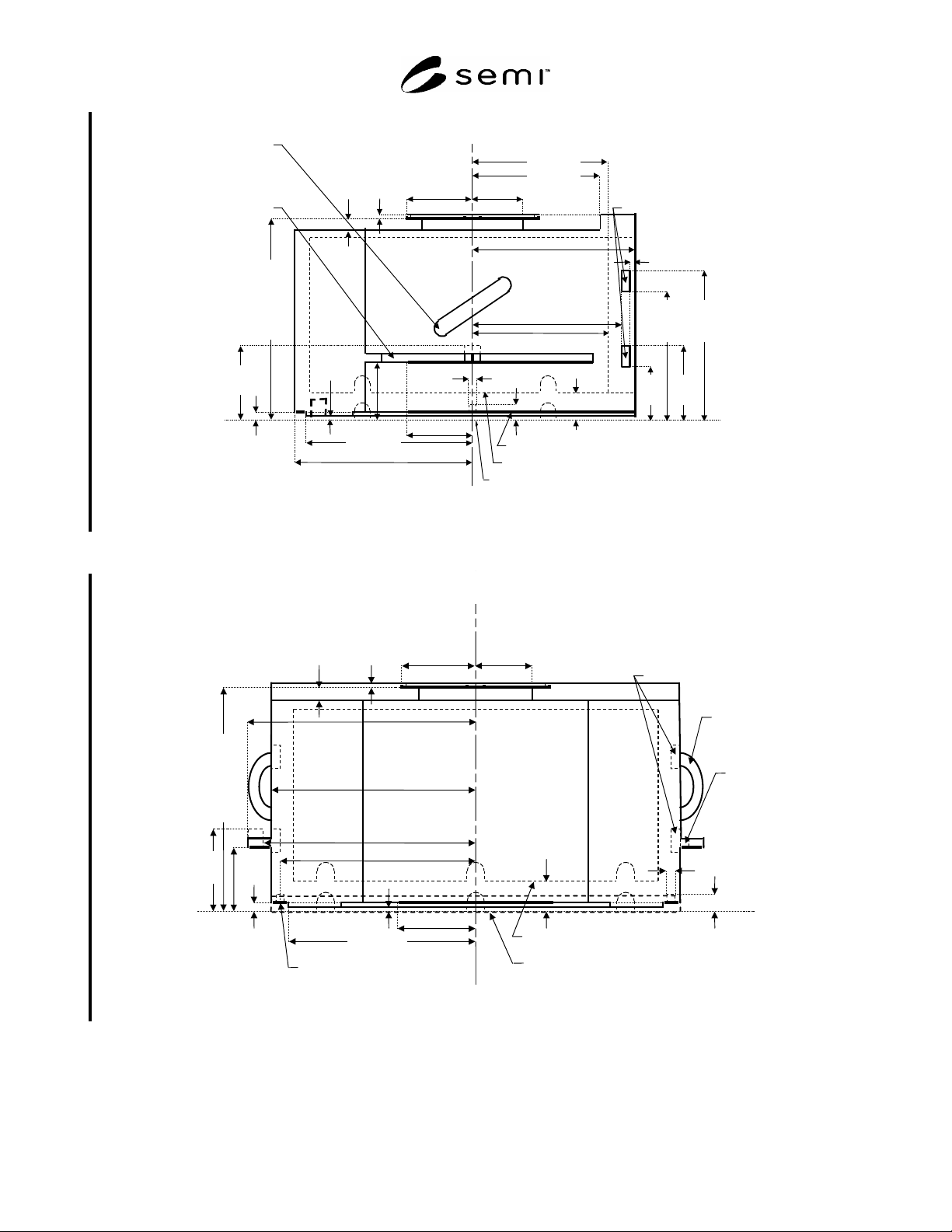
6.7 External Dimensions — Figures 5 through 8 show the side view, rear view, top view, and bottom view for the
FOUP. Table 1 defines all of the dimensions. In this and following figures, the heaviest lines are used for surfaces
that have tolerances (not surfaces that have only maximum or only minimum dimensions). If a FOUP identification
tag is used, it must be located at the bottom rear centered on the bilateral datum plane and must be contained within
the maximum outer dimensions of the FOUP.
NOTE 1: Figures 1 through 4 have been removed from this document.
SEMI E47.1-0305 © SEMI 1997, 2005 5
z
67
79.5
z
66
55.5
z
68
133.5
(253.5)
z
69
157.5
(277.5)
y
60
155
facial
datum plane
horizontal datum plane of FOUP nest or load port
horizontal datum plane inside FOUP
z
41
0
y
53
190
y
56 =189.75±0.25
(at bottom rail)
bottom conveyor rail
z
43 =2±1
y
58
75
y
50
130
y
51
140
z
44 =11±0
(numbers in parentheses are for 25-wafer FOUPs, if different)
y
57
178
y
46
=71±1
y
44
53
z
49
8
z
48
15
z
47
=210
(330)
±1
y
52 =165.5±0.5
(at seal zones, etc.)
166 (elsewhere)
d
65
=10±0.5
z
65
7
z
46
=60±1
z
59
72
human
handle
(optional)
side
fork-lift
flange
(optional)
y
61 =3.5±0.5
front clamp features
y
40 =122.5±2.5
Figure 5
Side View of FOUP
z
59
72
human
handle
(optional)
side
fork-
lift
flange
(optional)
bilateral datum plane
z
41
0
x
57
180
(numbers in parentheses are for 25-wafer FOUPs, if different)
z
43 =2±1
z
44
=11±0
horizontal datum plane
of FOUP nest or load port
horizontal datum plane inside FOUP
bottom conveyor rail
x
50 =214±1
(at side fork-lift flange)
x
56 =194.75
±0.25
(at bottom rail)
x
53
195
(elsewhere)
x
46
=71±1
x
44
53
z
49
8
z
48
15
z
47
=210
(330)
±1
x
58
75
d
65 =10±0.5
z
65
7
x
65 =187.5
z
46
=60±1
x
63 =199.3±1
front clamp feature
s
Figure 6
Rear View of FOUP