semi合集-English.pdf - 第1006页
SEMI E136-1104 © SEMI 2004 4 Figure 2 Calorimeter Calibration Connection Diagram 9.3.1 Use a calorimeter equipped with a coolant system. NOTE 5: Most calorim eter systems use either a tap-wa ter coolant system or a rec i…
SEMI E136-1104 © SEMI 2004 3
adequate lifting devices for large weights such as long
RF cables and generators themselves.
7.4 Persons performing tests should determine which
method of water cooling of the resistor in the RF
termination is utilized by the test device manufacturer
and should take steps to ensure safe use of the device.
7.4.1 Cooling-water flow rates should be appropriate to
the test device manufacturer’s recommendations for
cooling of the power load level being tested. Consult
the RF generator operating manual load specifications
for this information.
7.4.2 An RF termination using internal resistor cooling
only is highly recommended because such resistors (of
the tubular ceramic, thin film type) are usually cooled
by routing the coolant to the inside of the ceramic tube
and away from the resistive film, thereby eliminating
the possibility of electrolysis affecting the resistive
film.
7.4.3 In an alternative method, the coolant is routed on
both the inside and the outside of the resistor. While
this method provides for more efficient cooling, the
proximity of the coolant to the resistive film can
potentially result in damage to the resistive film caused
by electrolysis generated by the DC energy passing
through the fluid in the termination.
7.4.3.1 For this reason, if an RF termination using both
internal and external cooling is used, it is important to
periodically check the resistor for damage due to
electrolysis. This can be done easily by measuring the
resistance of the load resistor using a simple digital
multimeter.
7.4.3.2 With the RF termination disconnected from the
RF cable, place one probe on the center conductor of
the termination, and the other probe on the
termination’s outer conductor.
7.4.3.3 Measure the DC resistance of this path. If the
DC resistance is more than 53 , replace the resistor in
the termination.
7.5 In order to prevent the possibility of ground loops
between the RF generator and the calorimeter system,
be sure to operate the calorimeter and the RF generator
on the same AC supply.
8 Test Setup for RF Generator Power Output
Test
8.1 The test setup for the RF generator output power
test consists of the RF generator connected to the
calorimeter power meter through a length of coaxial
cable.
8.2 Prior to making any measurements, calibrate the
calorimeter power meter using a source of stable DC
energy.
9 Test Procedure for Determining RF
Generator Output Power
9.1 Calorimetric power meters provide excellent
reference standards for the measurement of RF energy
in that they are capable of measuring the true heating
power of a waveform, including any harmonic- or
nonharmonic-related frequency components. The
technique employed for this test is to first calibrate the
calorimetric power meter with DC energy, which can
be very precisely determined. Then, use two digital
multimeters (e.g., Fluke™ 87 or equivalent) to
determine the actual DC power applied to the
calorimeter. Finally, once the DC calibration has been
performed at a particular power level, connect the
output of the RF generator under test to the calorimeter
and measure the output power of the RF generator. The
basic steps involved in the use of this system are
outlined below.
9.2 Calibrate the Calorimeter — Calibrate the
calorimeter with the stable DC power supply, using the
two digital multimeters to read the voltage and current
applied to the calorimeter’s RF load.
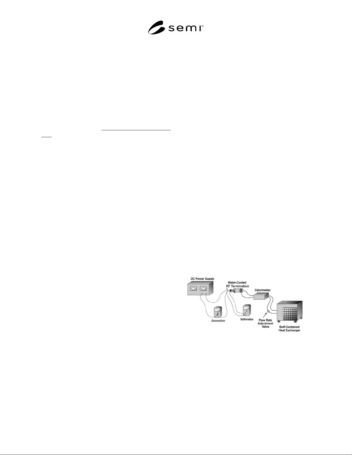
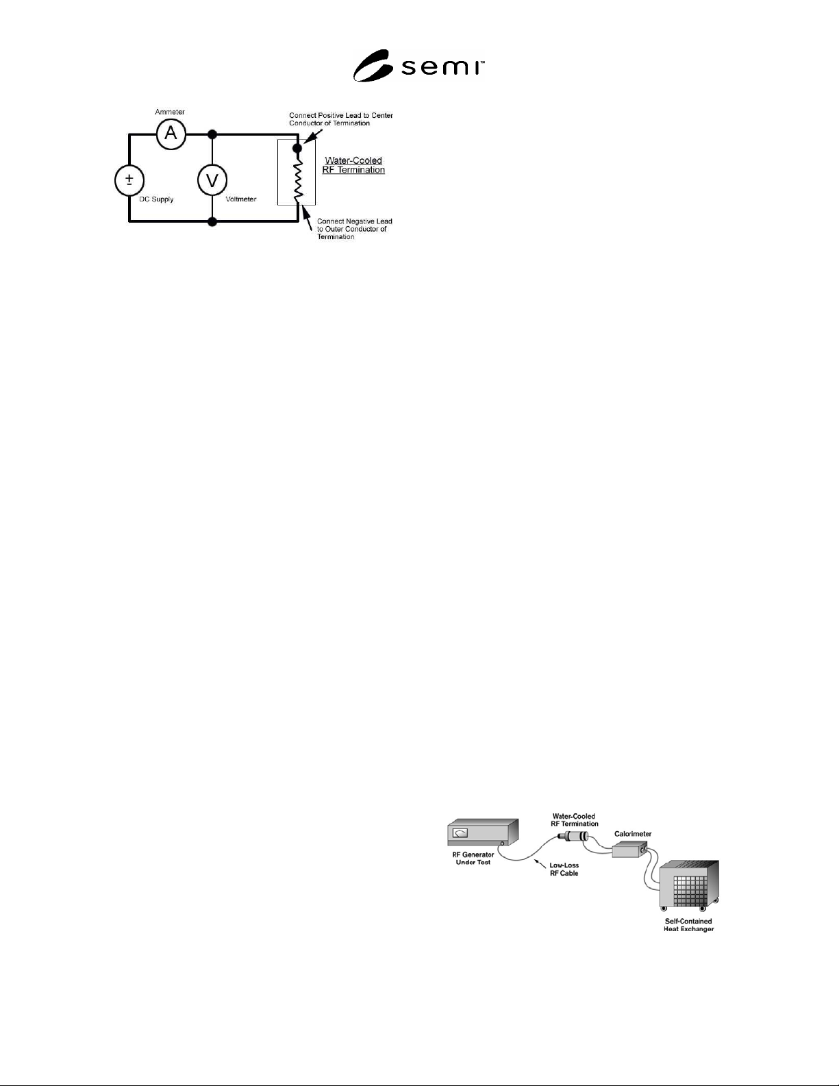
9.3 Connections — Connect the DC power supply, the
digital multimeters, and the RF load according to
Figures 1 and 2. Make the connections between the
multimeters, the DC power supply, and the RF load
using high-quality low-loss cable and high-quality
corrosion-free cable terminations.
Figure 1
Calorimeter Calibration Configuration
SEMI E136-1104 © SEMI 2004 4
Figure 2
Calorimeter Calibration Connection Diagram
9.3.1 Use a calorimeter equipped with a coolant
system.
NOTE 5: Most calorimeter systems use either a tap-water
coolant system or a recirculating system of some type. Best
results may be obtained through the use of a self-contained
heat exchanger and coolant recirculating system.
9.3.2 Make all of the electrical and coolant connections
to the calorimeter.
9.3.3 Apply main power to the calorimeter system and
allow one hour for stabilization.
9.3.4 Load Differential Temperature — Most
calorimeter systems will yield optimum performance
when certain operating parameters relating to the
differential temperature across the RF load and the flow
rate are maintained. In most cases, a differential
temperature of 2°C represents a good beginning point.
The coolant flow rate may then be set to provide for
this differential temperature.
9.3.4.1 The following formula may be used to arrive at
the correct coolant flow rate.
Power = 69.32 ×
T × Flow Rate (1)
where:
Power is in W,
T is in C, and
Flow Rate is in L/min.
9.3.4.2 Solving for flow rate yields:
Flow Rate = (Power / 69.32) /
T (2)
9.3.5 Coolant Types — In most cases, the coolant used
in calorimetric power measurement systems is pure
distilled water. In this case, most modern calorimeters
will automatically correct for changes to the coolant
physical characteristics (e.g., specific heat, specific
gravity) as the coolant temperature changes.
9.3.5.1 If coolant other than pure water is used and the
calorimeter chosen will not automatically compensate
for changes to the coolant, adjust the power readings
obtained for the effects of the coolant changes. Consult
the calorimeter operating manual for specific details.
9.3.6 Calorimeter Calibration — Following the
calorimeter warm-up, the device is ready for
calibration.
9.3.6.1 With the calorimeter operating at the
appropriate flow rate, apply DC power to the RF load,
according to the voltage and current readings obtained
with the two digital multimeters.
9.3.6.2 Multiply the voltage reading by the current
reading to obtain the power applied to the load.
9.3.6.3 Allow 15 minutes for the calorimeter reading to
stabilize.
9.3.6.4 Using the procedure in the calorimeter
operating manual, set the calorimeter such that the
calorimeter reading is exactly the same as that obtained
using the voltage and current meters.
9.3.6.5 At this point, add any offsets that are associated
with interconnecting cable losses, as outlined in
Sections 6.5.2 and 6.5.3.
9.3.6.6 The calorimeter is now calibrated at this
specific power level.
NOTE 6: If a new power level is selected, repeat this process
in order to compensate for instrumentation linearity effects of
the calorimeter.
9.3.7 RF Generator Testing — With the calorimeter
calibrated at a particular power level, it is now possible
to test the RF generator power output at this level.
9.3.8 Connections — Connect the RF generator output
to the RF load according to Figure 3. Use cables and
connectors between the RF generator output and the RF
load of a high-quality, low-loss type. As outlined
above, some power will be lost in the cables between
the generator and the load. Add these losses as offsets
to the calorimeter reading, in order to obtain the total
power output of the generator. Base the losses upon
cable length, cable type, and operating frequency. See
SEMI E114 test method for details on cable loss
compensation.
Figure 3
RF Generator Output Power Test

SEMI E136-1104 © SEMI 2004 5
9.3.9 Testing — With the connections made according
to Figure 2, apply main power to the RF generator and
allow 15 minutes for stabilization. The power reading
obtained on the calorimeter will represent the total
power output of the RF generator, including harmonics.
9.3.9.1 Begin RF generator testing at a power level that
represents 10% of the maximum output power of the
RF generator.
9.3.9.2 Repeat the test at RF generator power levels of
40% of maximum, 70% of maximum, and maximum
power.
9.3.9.3 Also, conduct tests corresponding to each range
on the RF generator power output meter.
NOTE 7: Calibrate the calorimeter power meter to the DC
standard at each power level used.
NOTICE: SEMI makes no warranties or
representations as to the suitability of the standards set
forth herein for any particular application. The
determination of the suitability of the standard is solely
the responsibility of the user. Users are cautioned to
refer to manufacturer's instructions, product labels,
product data sheets, and other relevant literature,
respecting any materials or equipment mentioned
herein. These standards are subject to change without
notice.
By publication of this standard, Semiconductor
Equipment and Materials International (SEMI) takes no
position respecting the validity of any patent rights or
copyrights asserted in connection with any items
mentioned in this standard. Users of this standard are
expressly advised that determination of any such patent
rights or copyrights, and the risk of infringement of
such rights are entirely their own responsibility.
Copyright by SEMI® (Semiconductor Equipment and Materials
International), 3081 Zanker Road, San Jose, CA 95134. Reproduction of
the contents in whole or in part is forbidden without express written
consent of SEMI.