semi合集-English.pdf - 第1519页
SEMI E32-0997 © SEMI 1994 , 1997 14 T RANS FE R, AT OM IC TR ANS FER AC TI VE , RESTORE, and AWAIT JOB COMPLET ION. SELE CT AT OM IC T RAN SF ER In this state, the next atomic transfer for this port is selected. Any prer…
SEMI E32-0997 © SEMI 1994, 199713
Committed To Transfer — The equipment informs the
host when it is fully prepared for a specific atomic
transfer. This signifies the completion of the setup
activities. It does not indicate that the two transfer
partners have agreed to begin the physical handoff. This
event coincides with the “Transfer Ready” message
defined in the micro level (see Section 5 below).
Atomic Transfer Started — The transfer partners
inform the host, via an event, when the atomic transfer
has begun
6
. This may represent a logical start rather
than physical movement. This indicates that any
necessary coordination of the transfer partners has been
done to ensure that the atomic transfer may start. A
secondary partner may sense the start of transfer later
than the primary partner.
NOTE 3: The physical transfer begins following the Atomic
Transfer Started event and ends prior to the Atomic Transfer
Complete event message.
Atomic Transfer Complete — This event indicates that
an atomic transfer has completed. This indicates that
either the next atomic transfer for this port will begin
the setup phase, or, if none remain, restore activities
may begin.
4.2.2 Transfer Job State Model — Message flow
diagrams are useful to show simple situations. Material
movement may range from very simple to quite
complex. The transfer job state model presented in this
section provides the information necessary to
extrapolate the message flow diagrams above to fit all
situations within the scope of this report. It does not
cover the states of the various hardware which may
exist (e.g., elevators, doors). See Section A1-1 for a
discussion of the port hardware and related
mechanisms.
The state model notation used in this report is that
defined by Harel and is described in a reference cited in
Section 1.3 above.
The transfer job is a transient entity. It is created by the
host (Transfer Job Create message), executes, and then
is dissolved by the equipment.
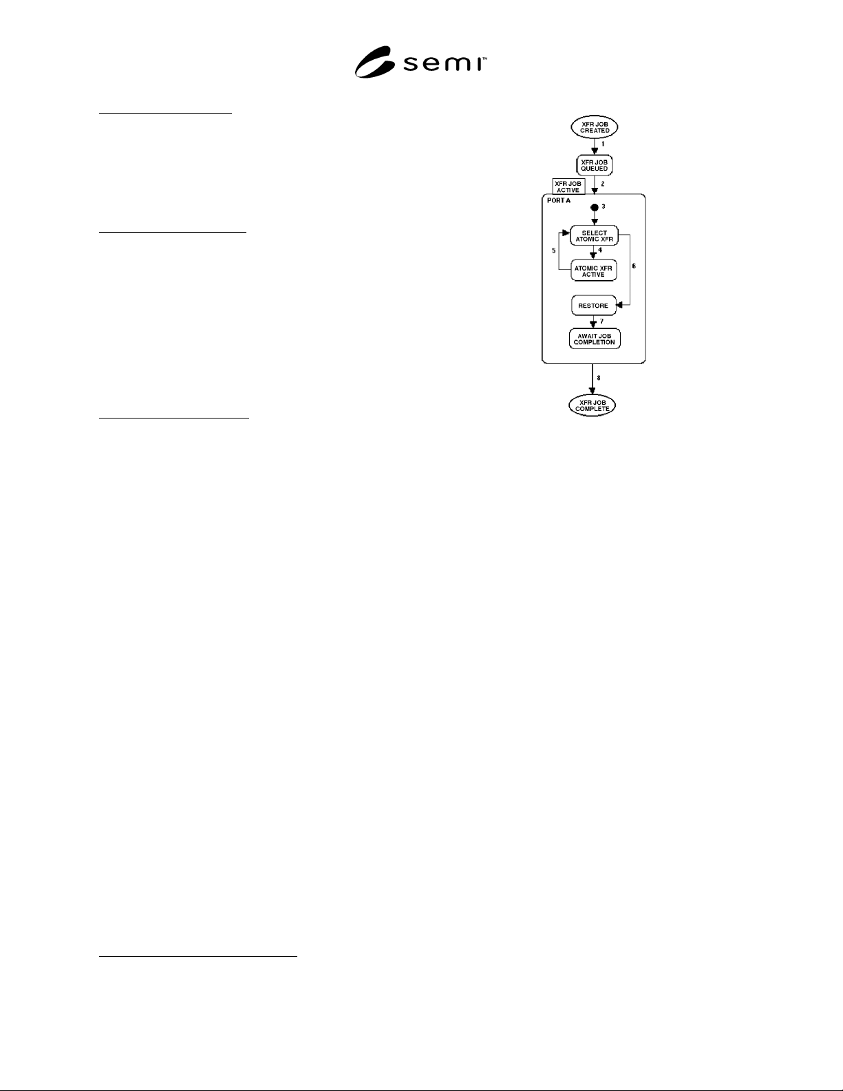
Figure 4.4 shows a basic state diagram for a transfer
job. The ovals at top and bottom show where the job is
created and then deleted. The portion between the ovals
is standard Harel notation. This model is from an
equipment view and assumes that only one port on the
equipment is used by the transfer. It also assumes that
pause, resume, abort, and stop activities do not exist
(these are addressed later in the document).
6 The primary transfer partner will determine readiness to start based
on micro level handshaking with the secondary transfer partner.
Figure 4.4
Transfer Job State Diagram for a Single Port
State definitions and then the state transition table
follow.
TRANSFER JOB QUEUED
In this state, the transfer job has been accepted by the
equipment through the Transfer Job
Create/Acknowledge messages and is awaiting
execution. Transfer jobs are begun sequentially in the
order received by the equipment. Execution may not
begin until all previously queued transfer jobs have
been started and the material locations needed for this
transfer job may be allocated.
All transfer jobs pass through this state. If the
equipment allows queuing of transfer jobs, they may
remain in this state for prolonged periods. A transfer
job remains queued until the material locations needed
for that transfer are available.
TRANSFER JOB ACTIVE
In the TRANSFER JOB ACTIVE state, all atomic
transfers defined in the transfer job are performed.
PORT A
This substate of TRANSFER JOB ACTIVE encloses
the job activities related to a single port on the
equipment. Within this state, the atomic transfers
involving this port are executed sequentially (except as
noted in Section 4.1.7 under Atomic Transfer
Sequencing Guidelines). Substates of PORT A (or
PORT B, etc.) include SELECT ATOMIC

SEMI E32-0997 © SEMI 1994, 1997 14
TRANSFER, ATOMIC TRANSFER ACTIVE,
RESTORE, and AWAIT JOB COMPLETION.
SELECT ATOMIC TRANSFER
In this state, the next atomic transfer for this port is
selected. Any prerequisites for the atomic transfer are
checked (e.g., is material XYZ in Port A, Location 1).
Atomic transfers are executed sequentially per port
(except as noted in Section 4.1.7 under Atomic Transfer
Sequencing Guidelines).
Prior to exiting this state, the port resources for the
selected atomic transfer are allocated.
If no atomic transfer is ready for selection (e.g., the port
resources are not available), the transfer job shall
remain in this state, awaiting a change in conditions
which would allow an atomic transfer to be selected.
ATOMIC TRANSFER ACTIVE
In this state, the next atomic transfer for this port is
executed. See the atomic transfer state model for details
on this process.
RESTORE
While in the RESTORE substate, the equipment shall
perform any necessary post–transfer operations to
return the port to the desired idle condition. These tend
to be physical activities. No physical actions are
required for restore, but some mechanism for
determining port status is recommended.
The setup
7
and restore operations are expected to be
“goal oriented,” that is, oriented toward satisfying
specific conditions (e.g., states such as “door open”).
They should not depend on a fixed sequence of actions
such as “initiate the door opening mechanism.” Thus, a
port left in a post–transfer condition from a previous
atomic transfer would still be able to prepare properly
for the next.
When queuing is allowed, the equipment may provide a
look ahead capability so it may alter its restore phase to
better accommodate the next transfer job. Such
functionality is not required.
AWAIT JOB COMPLETION
In this substate, all atomic transfers on this port for the
transfer job have completed. The transfer job continues
to exist until all ports have completed their atomic
transfers and restore operations. If only one port is
used, this state will be occupied only briefly.
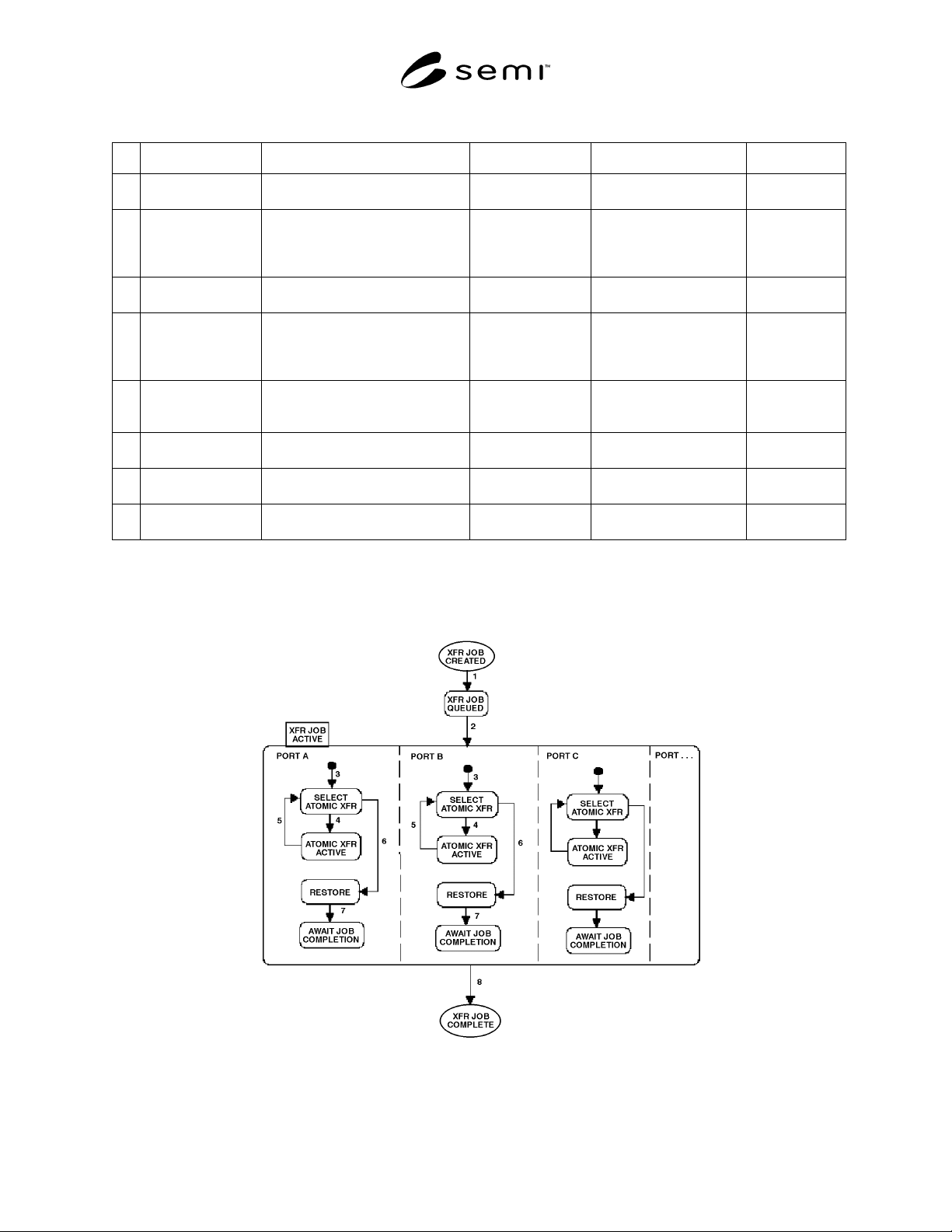
The following transition table defines the transitions
between states for the transfer job state model. It
applies to Figures 4.4 and 4.5.
7 Setup is more fully described in Section 4.2.3.
SEMI E32-0997 © SEMI 1994, 199715
Table 4.1 Transfer Job State Transition Table
# Current State Trigger New State Action(s) Comment
1 (Transfer Job
Created)
The equipment accepts a Transfer
Job from the host.
TRANSFER JOB
QUEUED
Place the transfer job in
the queue.
None.
2 TRANSFER JOB
QUEUED
Necessary material locations have
been allocated to transfer job and
any equipment-specific
prerequisites met.
TRANSFER JOB
ACTIVE
Remove the transfer job
from the queue. Send
“Transfer Job Started”
message.
None.
3 Any... Default entry into the PORT A (or
PORT B, etc.) state
SELECT ATOMIC
TRANSFER
All atomic transfers are
queued (by port).
None.
4 SELECT ATOMIC
TRANSFER
Atomic transfer selected for
execution on this port.
ATOMIC
TRANSFER
ACTIVE
Cause selected atomic
transfer to transition from
queued to setup.
See Sec. 4.2.3
for the atomic
transfer state
model.
5ATOMIC
TRANSFER
ACTIVE
Atomic transfer complete event
from the atomic transfer state
model.
SELECT ATOMIC
TRANSFER
None. None.
6 SELECT ATOMIC
TRANSFER
No atomic transfers remain for this
port.
RESTORE None. None.
7 RESTORE Port returned to desired idle
conditions.
AWAIT JOB
COMPLETION
None. None.
8 TRANSFER JOB
ACTIVE
All atomic transfers for the transfer
job are completed.
(Transfer Job
Complete)
Send “Transfer Job
Complete” message.
None.
Figure 4.5 begins with the model in Figure 4.4 and is expanded to cover a transfer job with multiple ports. Each
transfer job, as seen by the equipment, may include from one port to the total number of ports on the equipment.
Figure 4.5
Transfer Job State Model for Multiple Ports