semi合集-English.pdf - 第4584页
SEMI D34-0703 © SEMI 2003 2 5.1.2 Defect Measurement (Inspe ction) Method — Observe defect s under fluore scent light (600–1600 l ux), using either r eflection, tran smission, or Cross-Nicol transmission inspection, or a…

SEMI D34-0703 © SEMI 2003 1
SEMI D34-0703
TEST METHOD FOR MEASUREMENT OF FPD POLARIZING FILMS
This test method was technically approved by the Global Flat Panel Display Committee and is the direct
responsibility of the Japanese FPD Materials and Components Committee. Current edition approved by the
Japanese Regional Standards Committee on April 28, 2003. Initially available at www.semi.org May 2003;
to be published July 2003.
1 Purpose
1.1 This standard establishes implementation
guidelines for the measurement of visual appearance,
thickness, and optical characteristics of FPD Polarizing
Films. These methods can be applied in manufacturing,
quality control, and research and development.
2 Scope
2.1 This document specifies measurement methods.
2.2 Specifies measurement methods for visual
appearance (dot defects, line defects, visual exclusion
area), thickness, optical characteristics (single
transmittance, parallel transmittance, cross
transmittance, UV cut performance, polarization
efficiency, hue a, b and hue a*, b* and haze) of
polarizing films.
NOTICE: This standard does not purport to address
safety issues, if any, associated with its use. It is the
responsibility of the users of this standard to establish
appropriate safety and health practices and determine
the applicability of regulatory or other limitations prior
to use.
3 Referenced Standards
3.1 Japan Industry Standards (JIS)
1
JIS K7105
2
— Testing methods for optical
characteristics of plastics
JIS Z8701
3
— Colour specification -- The CIE 1931
standard colorimetric system and the CIE 1964
supplementary standard colorimetric system
JIS Z8720
4
— Standard Illuminants and sources for
colorimetry
1 Japan Standards Association(JSA) 4-1-24 Akasaka, Minato-ku,
Tokyo, 107-8440 Japan. Tel: +81-3-3583-8000, E-mail:
webmaster@jsa.or.jp, http://www.jsa.or.jp
2 English version available.
3 Related International Standards: CIE 15.2, ISO/CIE 10526: CIE
standard colorimetric illuminants, ISO/CIE 10527: CIE standard
colorimetric observers; Commission Internationale de l’Eclairage,
Kegelgasse 27, A-1030 Vienna, Austria. Tel: +43-1-714-31-87-0;
International Organization for Standards(ISO), 1, rue de Varembe,
Case, postale 56 CH-1211 Geneva 20, Switzerland. Tel: +41-22-749-
01-11, E-mail: central@iso.ch, http://www.iso.ch
JIS Z8723
5
— Methods for visual comparison of
surface colours
JIS Z8729
6
— Colour specification -- CIE LAB and
CIE LUV colour spaces
NOTICE: Unless otherwise indicated, all documents
cited shall be the latest published versions.
4 Terminology
None.
5 Definitions of Measured Object and
Summary of Measurement Methods
5.1 Visual Appearance of Polarizing Film (Dot
Defects)
5.1.1 Definition of Defect Size
5.1.1.1 Non-White Spot — Points that can be verified
visually during reflection inspection and transmission
inspection. Size is defined by measuring the long side
and short side of the core section and taking their mean
value (Φ).
5.1.1.2 White Spot — Points that can be verified
visually during Cross-Nicol transmission inspection.
Size is defined by measuring the long side and short
side of the core section and taking their mean value
(Ф).
A
B
φ
=
(
A+
B
)/2
Figure 1
Definition of Defect Size (Dot Defect)
4 Related International Standards: ISO/CIE 10526: CIE standard
colorimetric illuminants
5 Related International Standards: ISO/DIS 3668: Paints and
varnishes – Visual comparison of the colour of paints
6 Related International Standards: Not Applicable; English version
not available.
SEMI D34-0703 © SEMI 2003 2
5.1.2 Defect Measurement (Inspection) Method —
Observe defects under fluorescent light (600–1600 lux),
using either reflection, transmission, or Cross-Nicol
transmission inspection, or a combination of the above,
at approximately 30 cm from the sample.
5.1.2.1 Reflection Inspection: Conduct on a
blackboard, using fluorescent light.
5.1.2.2 Transmission Inspection: Conduct on a
backlight
5.1.2.3 Cross-Nicol: Place a reference polarizing film
on a backlight, and conduct transmission inspection in
transmission inspection Cross-Nicol state.
5.2 Polarizing Film Visual Appearance (Line Defects)
5.2.1 Defect Size Definition
5.2.1.1 Line defects visually detected during reflection,
transmission, or Cross-Nicol inspection. Size is defined
by measuring the length of the long side and short side.
W
L
Figure 2
Definition of Defect Size (Line Defect)
5.2.2 Defect Measurement (Inspection) Method —
Observe defects under fluorescent light, using either
reflection, transmission, or Cross-Nicol transmission
inspection, or a combination of the above, at
approximately 30 cm from the sample.
5.2.2.1 Reflection Inspection: Conduct on a
blackboard, using fluorescent light.
5.2.2.2 Transmission Inspection: Conduct on a
backlight
5.2.2.3 Cross-Nicol: Place a reference polarizing film
on a backlight, and conduct transmission inspection in
transmission inspection Cross-Nicol state.
5.3 Polarizing Film Visual Appearance (Visual
Exclusion Area)
5.3.1 Definition
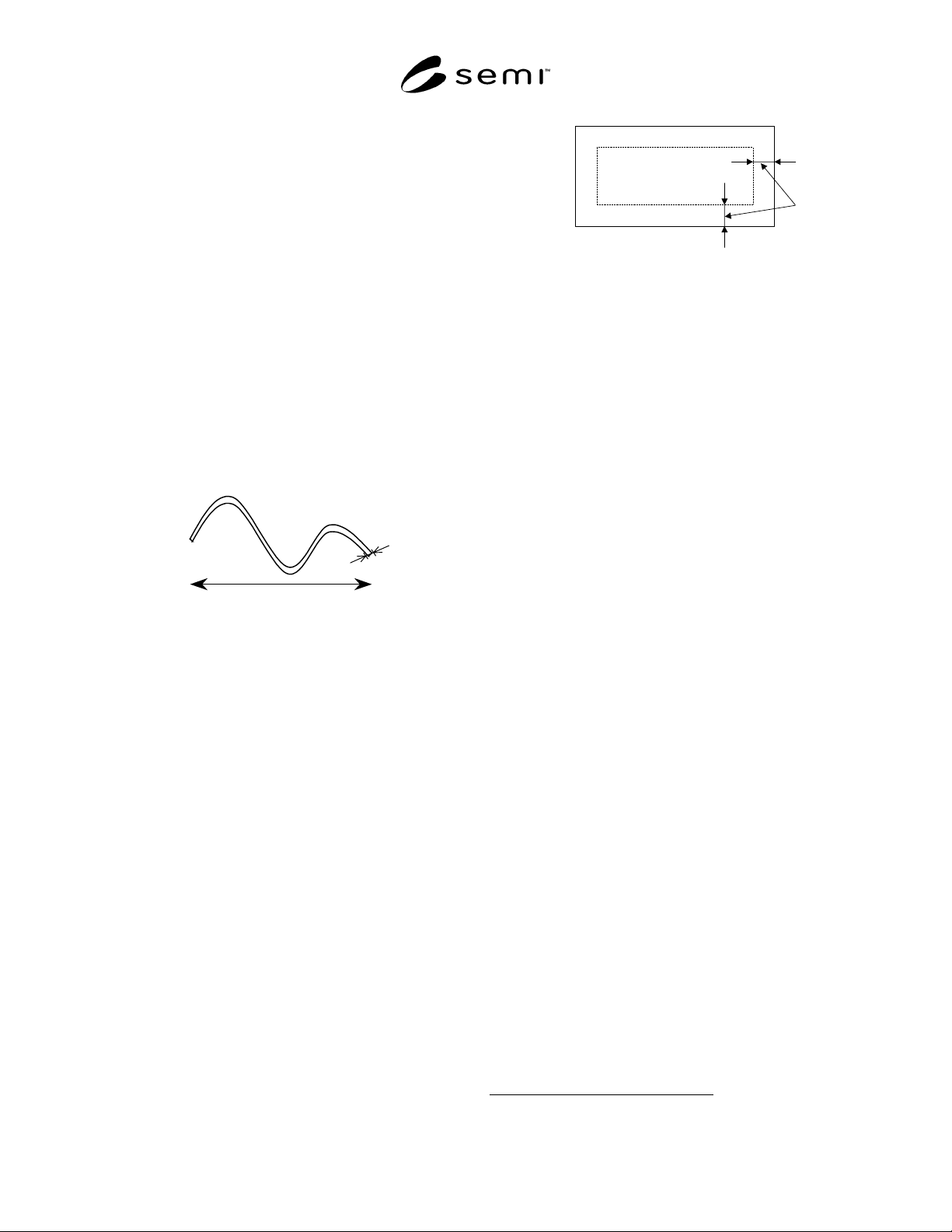
5.3.1.1 L of the Visual Exclusion Area is the
measurement of the distance from each side of the
polarizing film.
L
Figure 3
Definition of Visual Exclusion Area
5.4 Polarizing Film Thickness
5.4.1 Thickness Definition
5.4.1.1 Thickness, excluding the thickness of
protective film and separate film.
5.4.2 Thickness Measurement Method
5.4.2.1 Measured using a thickness gauge that can
measure to 0.001 mm.
5.5 Polarizing Film Optical Characteristics
5.5.1 Definition of Single Transmittance (Ty) and
Measurement Method
5.5.1.1 Value of Transmittance of 1 polarizing film,
visibility corrected (JIS Z8701) by supplementary
standard illuminant C (JIS Z8720)
7
, 2° range of view.
5.5.1.2 Measurement Conditions
5.5.1.2.1 Equipment: Spectrophotometer
5.5.1.2.2 Measurement Wavelength: 400–700 nm
(10 nm intervals)
5.5.2 Definition and Measurement Method of Parallel
Transmittance (T
//
)
5.5.2.1 Value of Transmittance of 2 polarizing films
placed parallel Nicol, visibility corrected (JIS Z8701)
by supplementary standard illuminant C (JIS Z8720),
2° range of view.
5.5.2.2 Measurement Conditions
5.5.2.2.1 Equipment: Spectrophotometer
5.5.2.2.2 Measurement Wavelength: 400–700 nm
(10 nm intervals)
5.5.3 Definition and Measurement Method for Cross
Transmittance (T
⊥
)
5.5.3.1 Value of Transmittance of 2 polarizing films
placed crossed Nicol, visually corrected (JIS Z8701) by
supplementary standard illuminant C (JIS Z8720), 2°
range of view.
7 Commonly known as “Light Source C”. Abbreviated to “Ill.C”.
SEMI D34-0703 © SEMI 2003 3
5.5.3.2 Measurement Conditions
5.5.3.2.1 Equipment: Spectrophotometer
5.5.3.2.2 Measurement Wavelength: 400–700 nm
(10 nm intervals)
5.5.4 Definition and Measurement Method for
Transmittance of each Wavelength
5.5.4.1 Measured value of 1 polarizing film at specific
wavelengths (440 nm, 550 nm, 610 nm)
5.5.4.2 Measurement Conditions
5.5.4.2.1 Equipment: Spectrophotometer
5.5.4.2.2 Measurement Wavelength: 440 nm, 550 nm,
610 nm
5.5.5 Definition and Measurement Method of UV Cut
Performance
5.5.5.1 Transmittance of 1 polarizing film, measured at
380 nm, is defined as UV cut performance.
5.5.5.2 Measurement Conditions
5.5.5.2.1 Equipment: Spectrophotometer
5.5.5.2.2 Measurement Wavelength: 380 nm
5.5.6 Definition and Measurement Method of
Polarization Efficiency (Py)
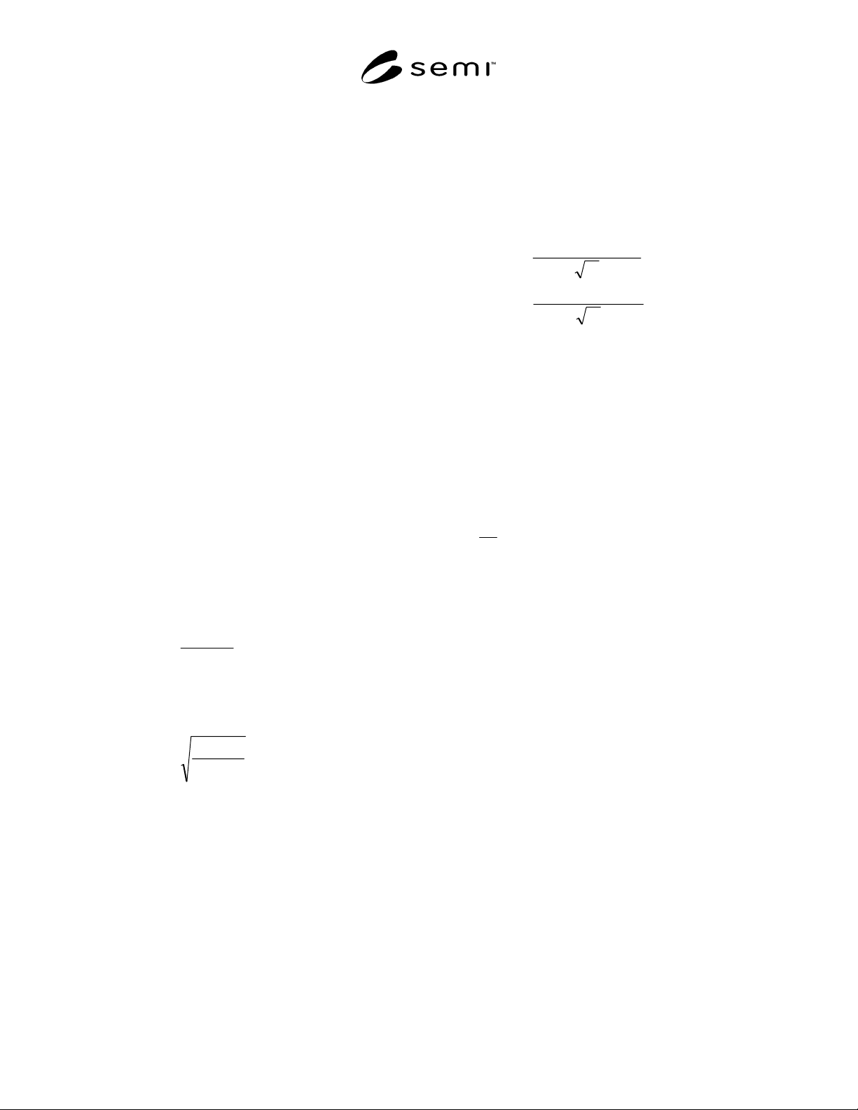
5.5.6.1 Expressed using the following formula, where
T
A
is transmittance (visibility corrected) on the
absorption axis, and T
B
is transmittance (visibility
corrected) on the transmittance axis.
AB
AB
TT
TT
Py
+
−
=
×100 (%)
5.5.6.2 The same value from the above equation can
also be calculated using the below equation, where T
//
is parallel transmittance and T
⊥
is cross transmittance.
⊥
⊥
+
−
=
TT
TT
Py
//
//
×100 (%)
5.5.6.3 Measurement Conditions
5.5.6.3.1 Equipment: Spectrophotometer
5.5.6.3.2 Measurement Wavelength: 400–700 nm
(10 nm intervals)
5.5.7 Definition and Measurement Method for Hue a*,
b*
5.5.7.1 Polarizing film transmittance value calculated
in accordance with JIS Z8729.
5.5.7.2 Measurement Conditions
5.5.7.2.1 Equipment: Spectrophotometer
5.5.7.2.2 Measurement Wavelength: 400~700 nm (10
nm intervals)
5.5.8 Definition and Measurement Method for Hue a, b
5.5.8.1 Visibility corrected (JIS Z8701) value by
supplementary standard illuminant C (JIS Z8720), 2°
range of view, calculated using the tristimulus values
(X, Y, Z) from the below formula.
(
)
Y
YX02.15.17
a
−
=
(
)
Y
Z847.0Y0.7
b
−
=
5.5.8.2 Measurement Conditions
5.5.8.2.1 Equipment: Spectrophotometer
5.5.8.2.2 Measurement Wavelength: 400–700 nm
(10 nm intervals)
5.5.9 Definition and Measurement Method for Haze
5.5.9.1 Scattered transmittance and all line
transmittance, measured using integrated sphere light
transmittance measurement equipment, expressed as a
ratio.
H =
t
d
T
T
×100 (%)
T
d
: Scattered Transmittance(%)
T
t
: All line transmittance(%)
To be measured in accordance with JIS K7105.
6 Equipment
6.1 Spectrophotometer with the below performance
shall be used.
6.1.1 Optical Wavelength: Sub 10 nm analysis
capability, adjustable between 380–780 mm.
7 Equipment Calibration
7.1 Equipment shall be calibrated in accordance with
the manufacturer’s manual.
7.2 When, due to calibration, there is a change in the
equipment’s performance, for example, linearity, phase
deviation, etc., a record shall be kept.
8 Related Document
8.1 Measurement Method for Optical Characteristics of
Polarizing Films Using Crystal Rotation Method