semi合集-English.pdf - 第6461页
SEMI G77-0699 © SE MI 1999 2 4.6 r obotic handling f lange hor i z ont al projection on the top of the frame cassette for lifting and ro tating the frame cassette. 4.7 t ape frame the frame which a ppl ies the wafer …

SEMI G77-0699 © SEMI 19991
SEMI G77-0699
SPECIFICATION FOR FRAME CASSETTE FOR 300 MM WAFERS
This test method was technically approved by the Global Assembly & Packaging Committee and is the direct
responsibility of the Japanese Packaging Committee. Current edition approved by the Japanese Regional
Standards Committee on March 17, 1999. Initially available at www.semi.org May 1999; to be published
June 1999.
1 Purpose
1.1 The purpose of this document is to specify the
mechanical features for a 300 mm wafer frame cassette
used between the wafer mounting process and the die-
bonding process.
2 Scope
2.1 This standard is intended to set an appropriate
level of specification that places minimal limits on
innovation while ensuring modularity and
interchangeability at all mechanical interfaces.
2.2 Only the physical interfaces for the frame cassette
are specified; no materials requirements or micro-
contamination limits are given. However, this
specification was written to allow for both metal and
plastic frame cassette designs.
2.3 This specification defines a 30 0 mm wafer frame
cassette that is intended for both manual and automated
transport. The frame cassette has the following
components and sub-components (“ ” indicates an
optional component):
2.3.1 Top
robotic handling flange (optional)
- top cover
2.3.2 Interior
- frame supports for 13 or 25 tape frames
- frame restraint
2.3.3 Sides
human handles (optional)
2.3.4 Rear
- rear cover
2.3.5 Bottom
- 2 bottom conveyor rails running along the
sides of the frame cassette
3 features that mate with kinematic coupling
pins and provide a 10 mm lead-in (optional)
4 frame cassette sending pads (optional)
3 Referenced Documents
3.1 SEMI Standards
SEMI E1.9 Provisional Mechanical Specification for
Cassettes Used to Transport and Store 300 mm Wafers
SEMI E15 Specification for Tool Load Port
SEMI E47.1 Provisional Mechanical Specification
for Boxes and Pods Used to Transport and Store 300
mm Wafers
SEMI E57 Provisional Mechanical Specification for
Kinematic Couplings Used to Align and Support 300
mm Wafer Carriers
SEMI G74 Specification for Tape Frame for 300
mm Wafers
SEMI S8 Safety Guidelines for Ergonomics/Human
Factors Engineering of Semiconductor Manufacturing
Equipment
4 Terminology
4.1 bilaterial datum plane
a vertical plane that
bisects the tape frames and that is perpendicular to both
the horizontal and facial datum planes (as defined in
SEMI E57).
4.2 conveyor rails
parallel surfaces on the bottom
of the cassette for supporting the cassette on roller
conveyors.
4.3 facial datum plane a vertical plane that bisects
the tape frames and that is parallel to the front side of
the frame cassette (where tape frames are removed or
inserted). On tool load ports, it is also parallel to the
load face plane specified in SEMI E15 on the side of
the tool where the frame cassette is loaded and
unloaded (as defined in SEMI E57).
4.4 frame cassette an open structure that holds one
or more tape frames.
4.5 horizontal datum plane a horizontal plane from
which projects the kinematic coupling pins on which
the frame cassette sits. On tool load ports, it is at the
load height specified in SEMI E15 and might not be
physically realized as a surface (as defined in SEMI
E57).

SEMI G77-0699 © SEMI 1999 2
4.6 robotic handling flange horizontal projection
on the top of the frame cassette for lifting and rotating
the frame cassette.
4.7 tape frame the frame which applies the wafer
tape to the wafer and retains the wafer.
4.8 wafer tape an adhesive plastic tape which
retains the wafer or diced chip. It is used between the
mounting process and die-bonding process.
5 Ordering Information
5.1 Intended use This document is intended to
specify 300 mm wafer frame cassettes over a
reasonable lifetime of use, not just those in new
condition. For this reason, the purchaser needs to
specify a time period as well as the number and type of
uses to which the frame cassettes will be put. It is under
these conditions that the frame cassettes must remain in
compliance with the requirements listed in Section 6.
6 Requirements
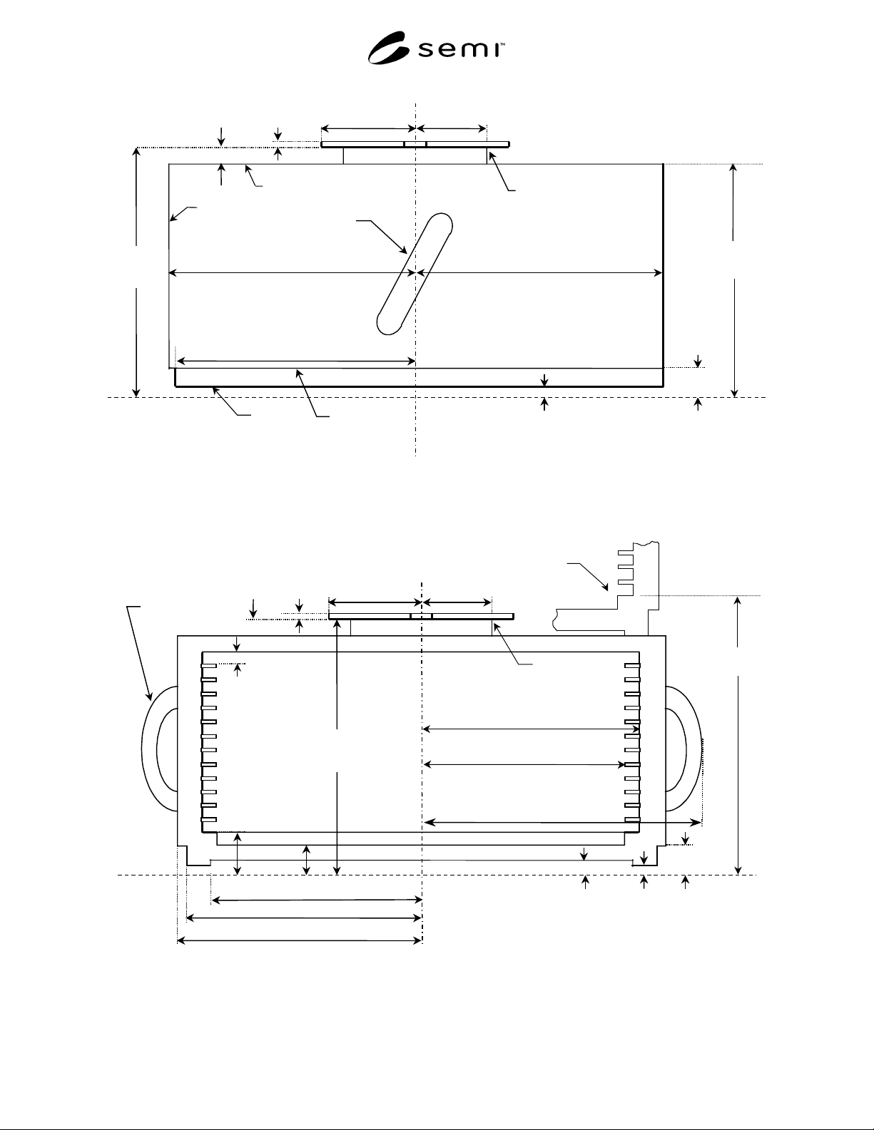
6.1 Dimensions The frame cass ette dimensions are
shown in Figures 1 through 5 and listed in Table 1. In
all figures, the heaviest lines are used for surfaces that
have tolerances (not surfaces that have only maximum
or only minimum dimensions).
6.2 Tape Frame Orientation The tape frames must
be horizontal when the frame cassette is placed on the
load port.
6.3 Center of Tape Frames When a tape frame is
stored in the frame cassette, the center of the tape frame
should be within the radius of 2 mm from the center of
the junction of the bilaterial datum plane and the facial
datum plane.
6.4 Top and Rear Covers Both top and rear covers
are required. With the covers in place, the frame
cassette must conform to all dimensions listed in Table
1.
6.5 Number of Slots The frame cassette has an
option of either 13 or 25 slots.
6.6 Kinematic Couplings (optional) The physical
alignment mechanism from the frame cassette to the
tool load port (or a nest on a vehicle or in a stocker)
consists of features (not specified in this document) on
the top entity that mate with three or six pins
underneath as defined in SEMI E57. Most of the
dimensions of the frame cassette are determined with
respect to the three orthogonal datum planes defined in
that standard: the Horizontal Datum Plane, the facial
datum plane, and the bilateral datum plane.
6.6.1 The three features that mate with the pins must
provide a lead-in capability that corrects a frame
cassette misalignment of up to 10 mm in any horizontal
direction, although 15 mm is recommended for
ergonomic reasons. However, it is recommended that
robotics placing cassettes on kinematic couplings use as
little of this lead-in capability as possible to avoid wear.
6.7 Human Handles (optional) All handles for use
by humans must either be contained within the
maximum outer dimensions of the frame cassette, be
detached when not in use, or be retractable into the
maximum outer dimensions when not in use. Handles
for use by humans (if present) must follow SEMI S8
and shall require the use of both hands (each using a
full wrap-around grip, given the minimum clearance
requirement in SEMI E15.1). Automation handling
features shall not be considered for dual purpose unless
they are designed to meet SEMI S8.
6.8 Robotic Handling Flange (optional) On the top
of the frame cassette is an optional robotic handling
flange for manipulating the frame cassette.
6.9 Bottom Rails On the bottom of the frame
cassette are two rails, one on each side for use with
roller conveyors.
6.10 Frame Restraint The frame cassette must
provide a feature that prevents tape frames from
slipping out of the cassette during transport. The feature
must conform to all dimensions listed in Table 1.
6.11 Frame Cassette Sensing Pads (optional)
When the cassette is fully down, the frame cassette
sensing pads (see Figure 5) must be z2 above the
horizontal datum plane. It is recommended that the
areas surrounding all of the frame cassette sensing pads
be designed in conjunction with the features that mate
with the kinematic coupling pins so that a mechanical
sensor pin cannot interfere with the lead-in function of
the kinematic couplings.
6.12 Cassette Stacking (optional) The frame
cassette may have optional features to allow two 13
capacity cassettes to be stacked on top of each other.
This option is only available for cassettes without a
robotic handling flange.
SEMI G77-0699 © SEMI 19993
horizontal
datum plane
y
46 = 71
±
1
y
44
≤
53
z
49
≤
8
z
48
≥
15
facial
datum plane
z
47
= 210
(330 )
±
1
y
5
≤
200
y
1 = 193
±
0.25
z
43 = 1
z
8
≥
15
top of x,y
dimension
control area
robotic handling
flange (optional)
human handle
(optional)
+0
-1
rear cover
y
2 =193
±
0.25
top cover
z
1
≤ 183
(303 )
bottom
rail
Figure 1
Side View of Frame Cassette
horizontal
datum
plane
x
46 = 71
±
1
x
44
≤
53
z49
≤
8z48
≥
15
bilateral
datum plane
z43 = 1
z41
≥
1
z8
≥
15
z47
= 210
(330 ) ±
1
x57
≤
187
x
1
≤
203.5
x
56 = 194.75
±
0.25
x2
≤
240(at human handle)
z4 = 33
z3
≤
23
z7
≥
10
robotic handling
flange (optional)
human handle
(optional)
x
4 = 191.5
±
0.3
187
≥
x
3
≥
177
+0
-1
z9 = 215
(stacking)
13 slot cassette
stacking (optional)
Figure 2
Front View of Frame Cassette