semi合集-English.pdf - 第7391页
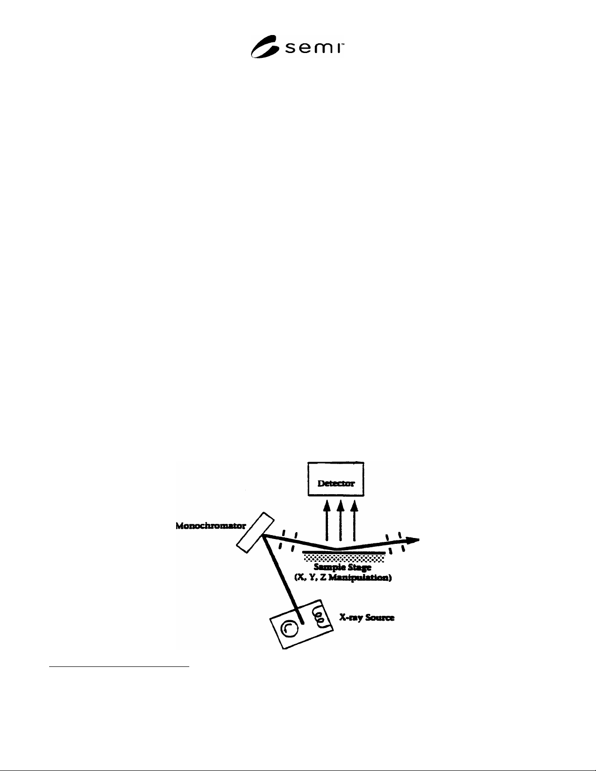
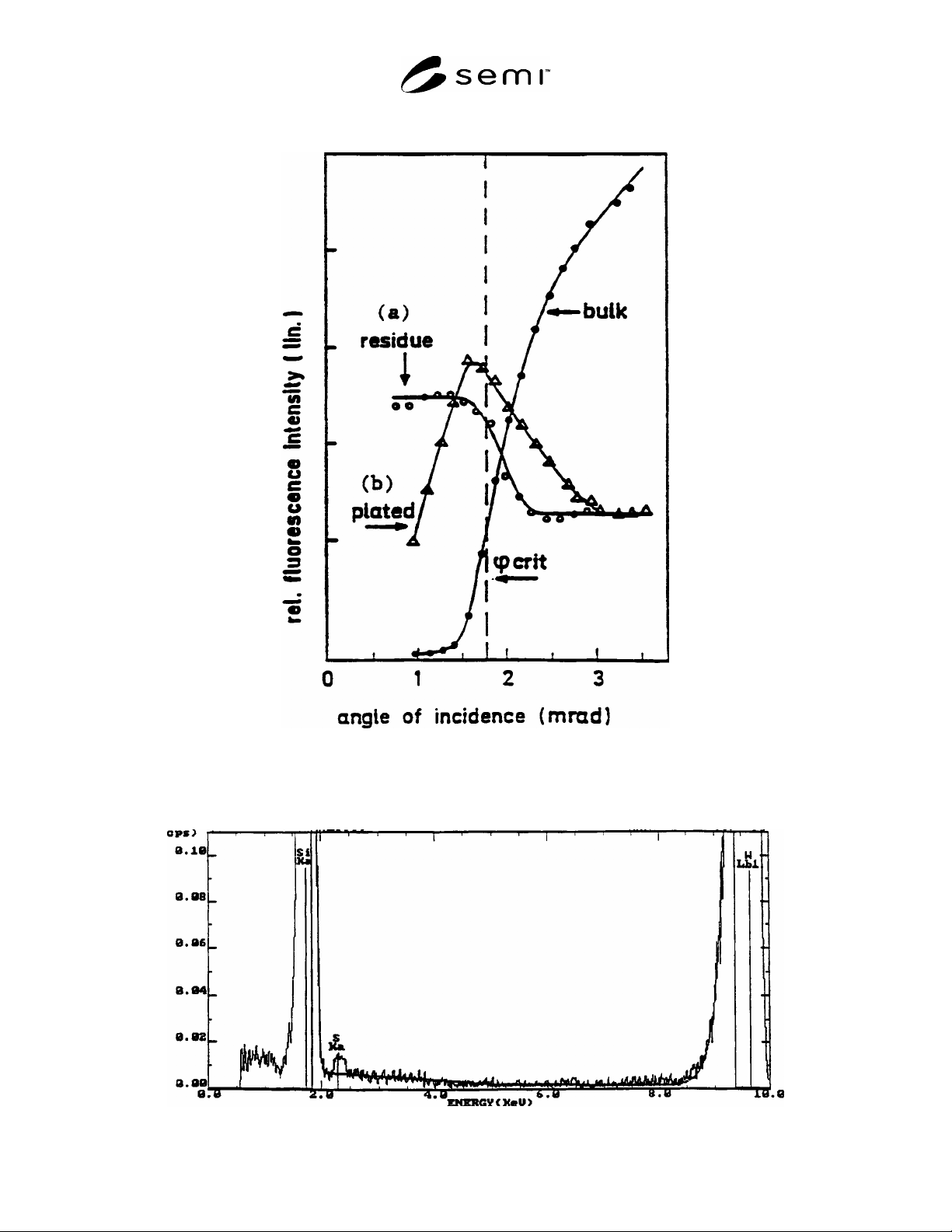
SEMI MF1526-95 © SEMI 2004 7 FIG. 1 Block Diagram of the TXRF Technique FIG. 2 Experimental Curve s for the Angular Dependence of the Fluorescence Intensity fr om Pl ated or Sput tered Submonoatomic Nickel-layers ( ), …
SEMI MF1526-95 © SEMI 2004 6
14.1.3 Anode material,
14.1.4 Monochromator,
14.1.5 Operator,
14.1.6 Date,
14.1.7 Type of instrument including model and manufacturer,
14.1.8 Software version,
14.1.9 Analysis time, and
14.1.10 Crystal orientation of the test specimen with respect to the incoming X-ray beam.
15. Precision and Bias
11
,
12
15.1 Precision—The precision was estimated through two round robins using monochromatic TXRF instruments.
15.1.1 The within-laboratory precision was estimated from a sequential round robin
12
that used two reference samples and
six unknowns with surface contamination of iron, nickel, copper and zinc, between 10
11
and 10
12
atoms/cm
2
. Thirteen
laboratories participated. At each laboratory the samples were measured once per day for 4 days. The measurement conditions
were X-ray rotating anode with a tungsten target, LiF (200) monochromator (9.67 keV line selected), 30 kV, 200 mA,
glancing angle of 0.05°, 10
2
torr ambient, 10-mm diameter analysis area, and 1000-s integration time. The data were reported
by each laboratory as the average of the four readings and the one standard deviation of the four readings. The 95 %
confidence, within-laboratory relative precision was 28 %, that is, 2.8 times the within-laboratory relative one standard
deviation of 10 %.
15.1.2 The between-laboratory precision was estimated from a spoke wheel round robin
13
that used sets of one reference
sample and three unknowns, one of which was a BLANK. The reference sample and the unknowns were contaminated with
surface nickel between 10
11
and 10
12
atoms/cm
2
. Seventeen organizations participated. At each laboratory the samples were
measured on multiple days. The measurement conditions were X-ray rotating anode with a tungsten or gold target,
monochromator (9.67 keV or higher line selected), 30 kV, 200 mA or higher, glancing angle of 0.1°, 10-mm diameter analysis
area, and 1000-s integration time. The 95 % confidence between-laboratory precision was: ±8 × 10
10
atoms/cm
2
at an
average 15 × 10
10
atoms/cm
2
, and ±20 × 10
10
atoms/ cm
2
at an average 45 × 10
10
atoms/cm
2
.
15.1.3 Analysis conditions other than those used for these round robins listed in 15.1.1 and 15.1.2 can be used, but the
precision has not been estimated for other analysis conditions.
15.2 Bias—The bias of this test method cannot be estimated, because there are no absolute standards for this test method.
16. Keywords
16.1 contamination; metals; silicone; surface; TXRF; X-ray fluorescence
11 Hockett, R. S., Ikeda, S., and Taniguchi, T., “TXRF Round Robin Results,” Cleaning Technology in Semiconductor Device Manufacturing, ECS
Proceedings, edited by J. Ruzyllo and R. E. Novak, Vol 92-12, The Electrochemical Society, Pennington, NJ, 1992, pp. 324–337.
12 Supporting data are available from ASTM Headquarters. Request RR: F01-1009 and F01-1012.
SEMI MF1526-95 © SEMI 2004 7
FIG. 1 Block Diagram of the TXRF Technique
FIG. 2 Experimental Curves for the Angular Dependence of the Fluorescence Intensity from Plated or Sputtered
Submonoatomic Nickel-layers (), Layers Produced by Evaporation of a Nickel Salt Solution (O) and the Silicon
Substrate (·)

SEMI MF1526-95 © SEMI 2004 8
FIG. 3 Example BLANK (Except for Sulfur) Spectrum of Silicon Wafer Using TREX 610 Operated at 30 kV, 200
mA, 0.11°, 1000 s, Tungsten Target, LiF (200) Monochromator, W L-beta Line (9.67 keV)