semi合集-English.pdf - 第4588页
SEMI D34-0703 © SEMI 2003 6 R1-3.3 Definition for Parallel Transmittan ce (T // ) Parallel transmittance light Tp ( λ ): 2 ) ( K ) ( K ) ( 2 B 2 A λ λ λ + = Tp Parallel transmittance T // : Value of Tp ( λ ) visibility c…
SEMI D34-0703 © SEMI 2003 5
RELATED INFORMATION 1
MEASUREMENT METHOD FOR OPTICAL CHARACTERISTICS OF
POLARIZING FILMS USING CRYSTAL ROTATION METHOD
NOTICE: This related information is not an official part of SEMI D34 and was derived from Otsuka Electronics
Co., Ltd. This related information was approved for publication by full letter ballot procedures.
R1-1 Outline
R1-1.1 This method is not to use two polarizing film in normal, but to use polarizing prism and one polarizing film,
which can be used for measurement of Single transmittance (Ty), Parallel transmittance (T
//
), Cross transmittance
(T
⊥
), Transmittance of each wavelength, UV cut performance, Polarizing Efficiency (Py) and Hue a, b.
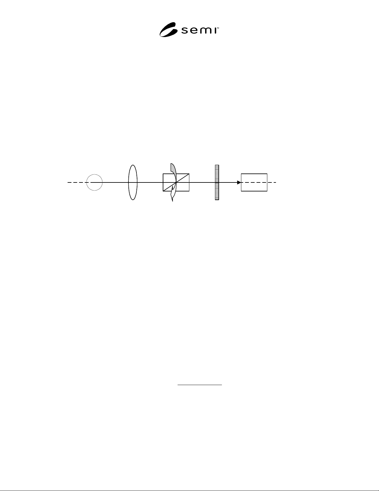
R1-1.2 Equipments are shown below. Measurement condition is same as standard method.
R1-2 Measurement Equipment
Light Source Lens Polarizing prism Polarizing film Spectrophotometer
R1-3 Formula
R1-3.1 K
A
(λ) is measured on condition of polarizing prism and polarizing film placed perpendicularly and K
B
(λ) is
measured on condition of polarizing prism and polarizing film placed parallel, where K
A
(λ) is transmittance light on
the absorption axis and K
B
(λ) is transmittance light on the transmittance axis.
K
A
(λ) = S
//
(λ) / R
//
(λ)
K
B
(λ) =S
⊥
(λ) / R
⊥
(λ)
S
//
(λ): Light intensity of transmittance on condition of polarizing film and polarizing prism placed parallel with
polarizing film.
R
//
(λ): Light intensity of transmittance without polarizing film on same condition of S
//
(λ).
S
⊥
(λ): Light intensity of transmittance on condition of polarizing film and polarizing prism placed perpendicularly
with polarizing film.
R
⊥
(λ): Light intensity of transmittance without polarizing film on same condition of S
⊥
(λ).
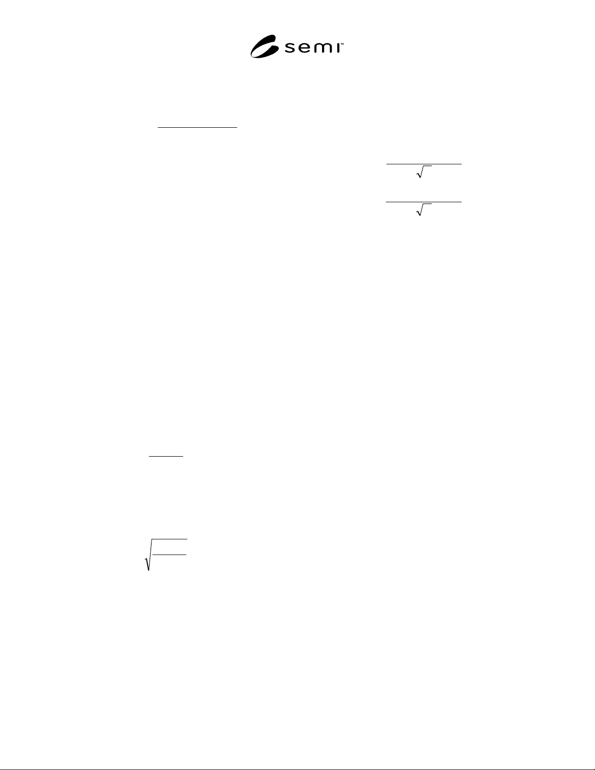
R1-3.2 Definition for Single Transmittance (Ty)
Single transmittance light Ts(λ):
Single transmittance Ty: Value of Ts(λ) visibility corrected (JIS Z8701).
2
)(K)(K
)(
BA
λλ
λ
+
=Ts
SEMI D34-0703 © SEMI 2003 6
R1-3.3 Definition for Parallel Transmittance (T
//
)
Parallel transmittance light Tp (λ):
2
)(K)(K
)(
2
B
2
A
λλ
λ
+
=Tp
Parallel transmittance T
//
: Value of Tp (λ) visibility
corrected (JIS Z8701).
R1-3.4 Definition of Cross Transmittance (T
⊥
)
Cross transmittance light Tc (λ): Tc (λ) = K
A
(λ) × K
B
(λ)
Cross transmittance T
⊥
:
Value of Tc (λ) visibility
corrected (JIS Z8701).
R1-3.5 Definition for Transmittance of Each
Wavelength
Value of Single Transmittance Ts (λ) at the wavelength
of 440 nm, 550 nm and 610 nm.
R1-3.6 UV Cut Performance
Value of Single Transmittance Ts (λ) at the wavelength
of 380 nm.
R1-3.7 Definition for Polarizing Efficiency (Py)
R1-3.7.1 Value calculated from following formula
same as standard method, where the value of
transmittance light K
A
(λ) (visibility corrected) on the
absorption axis is transmittance T
A
on the absorption
axis, and transmittance light K
B
(λ) (visibility corrected)
on the transmittance axis is transmittance T
B
on the
transmittance axis.
(%) 100×
+
−
=
AB
AB
TT
TT
Py
R1-3.7.2 Same as the standard method, Py is calculated
from the Parallel transmittance (T
//
) and Cross
transmittance (T
⊥
) using the latter formula which is
equivalent with the former formula.
(%) 100
//
//
×
+
−
=
⊥
⊥
TT
TT
Py
R1-3.8 Definition for Hue a. b.
R1-3.8.1 Value calculated from below formulas same
as standard method using the tristimulus values (X, Y,
Z) obtained from Single spectra-transmittance Ts (λ)
visibility corrected (JIS Z8701) by light source C at 2°
range of view.
Y
YX
a
)02.1(5.17 −
=
Y
ZY
b
)847.0(0.7
−
=
R1-4 Related Documents
The Kogyo Zairyo Vol. 28 –7 P.37~P.45
NOTICE: SEMI makes no warranties or
representations as to the suitability of the standards set
forth herein for any particular application. The
determination of the suitability of the standard is solely
the responsibility of the user. Users are cautioned to
refer to manufacturer’s instructions, product labels,
product data sheets, and other relevant literature
respecting any materials mentioned herein. These
standards are subject to change without notice.
The user’s attention is called to the possibility that
compliance with this standard may require use of
copyrighted material or of an invention covered by
patent rights. By publication of this standard, SEMI
takes no position respecting the validity of any patent
rights or copyrights asserted in connection with any
item mentioned in this standard. Users of this standard
are expressly advised that determination of any such
patent rights or copyrights, and the risk of infringement
of such rights, are entirely their own responsibility.
Copyright by SEMI® (Semiconductor Equipment and Materials
International), 3081 Zanker Road, San Jose, CA 95134. Reproduction o
f
the contents in whole or in part is forbidden without express written
consent of SEMI.
SEMI D35-1103
E
© SEMI 2003 1
SEMI D35-1103
E
TEST METHOD FOR MEASUREMENT OF COLD CATHODE
FLUORESCENT LAMP (CCFL) CHARACTERISTICS
This test method was technically approved by the Global Flat Panel Display Committee and is the direct
responsibility of the Japanese Flat Panel Display Committee. Current edition approved by the Japanese
Regional Standards Committee on August 8, 2003. Initially available at www.semi.org October 2003; to be
published November 2003.
E
This standard was editorially modified in November 2004 to correct editorial errors. Changes were made to
multiple sections, figures, and tables.
1 Purpose
1.1 The purpose of this document is to standardize the
method for measurement of electrical and optical
characteristics of cold cathode fluorescent lamp
(CCFL).
2 Scope
2.1 This method is to be used by CCFL suppliers and
users to evaluate quality of products as well as items
under development.
2.2 This method shall be used in general for CCFL to
measure the initial characteristics of CCFL (single
item) and its reliability after tests, and to carry out
quality inspection for incoming and outgoing CCFLs.
NOTICE: This standard does not purport to address
safety issues, if any, associated with its use. It is the
responsibility of the users of this standard to establish
appropriate safety and health practices and determine
the applicability of regulatory or other limitations prior
to use.
3 Referenced Standards
3.1 JIS Standards
1
JIS Z 8113 — Lighting vocabulary
3.2 IEC Standards
2
IEC 60050 (845) — Lighting, Section 1: Radiation,
Quantities and Units, 3: Colorimetry
NOTICE: Unless otherwise indicated, all documents
cited shall be the latest published versions.
1 Japanese Standards Association, 1-24, Akasaka 4 Chome, Minato-
Ku, Tokyo, 107-8840 Japan. Tel: +81-3-3583-8000, E-mail:
webmaster@jsa.or.jp, http://www.jsa.or.jp
2 International Electrotechnical Commision(IEC), 3, rue de
Varembé , P.O. Box131 CH-1211 Geneva 20, Switzerland. Tel: +41-
22-919-02-11, E-mail: iec@iec.ch, http://www.iec.ch
4 Terminology
4.1 Abbreviations and Acronyms
4.1.1 CCFL — Cold Cathode Fluorescent Lamp
4.2 Definitions
4.2.1 effective emission area — an area (length) in
which a certain percentage of luminance against the
luminance of a central part is maintained with almost
even luminance distribution (LE[mm]).
4.2.2 lamp current — effective current inside the lamp
(IL[mArms]). (The GND side shall be measured.)
4.2.3 lamp voltage — effective voltage across both
ends (between two electrodes) of a lamp at rated lamp
current (VL[Vrms]).
4.2.4 lamp wattage — a product of the lamp current,
lamp voltage and a power factor. A reference value
(W[Wrms]).
4.2.5 luminance stabilization time — the time to reach
a certain percentage of the luminance of a central part
(Ts[min.]).
4.2.6 stable discharge voltage — effective voltage at
lamp ends (between two electrodes) when a main
discharge starts (Es[Vrms]).
5 Summary of Method
5.1 Warm up the measuring equipment for a specified
period of time to stabilize (according to the instruction
manual of measuring equipment).
5.2 Keep the lamp wall temperature of a CCFL and the
ambient temperature in equilibrium. The ambient
temperature shall be stable.
5.3 Set the CCFL on the measuring equipment.
5.4 Adjust the point of measurement (viewing angle),
focus and distance.
5.5 Measure the stable discharge voltage.
5.6 Turn on the CCFL by applying a rated current and
measure the lamp current when it is stable.