semi合集-English.pdf - 第922页
SEMI E118-1104 E © SEMI 2002, 2004 16 R2-3 Full Capabilities R2-3.1 Figure R2-2 shows the object model for a WIDR with full cap abilities, so that all o ptional attributes and services are supported. 1+ WIDR - Alar mStat…
SEMI E118-1104
E
© SEMI 2002, 2004 15
RELATED INFORMATION 2
OBJECT MODEL
NOTE: This related information is not an official part of SEMI E118 and was derived from work of the originating
task force. This related information was approved for publication by full letter ballot procedures on July 19, 2002
R2-1 Object Model Notes
R2-1.1 Object models provide a graphic representation of entities. The models in this section use the Object
Modeling Technique (OMT) described in Object-Oriented Modeling and Design. Object types are represented by
rectangles with one, two, or three sections. The name of the object type is in the first, or only section. Attributes,
information about the object, are shown in the second section. Operations or services are shown in a third section.
Lines between objects represent relationships.
R2-1.2 Three models are shown for purposes of illustration. The general multi-head case is shown first with only
the required attributes and services. Next, the full model for the multi-head case is shown with all attributes and
services defined in this standard. Finally, the full model for the integrated single-head case is shown.
R2-1.3 Note that the Upstream Controller sends all service requests to the WIDR controller, including services
shown for the individual heads. Services shown on these models for WIDR are those with a Head ID service
parameter value of zero while services shown for the Head are those with a Head ID service parameter value
between one and thirty-one.
R2-2 Fundamental Requirements Example Object Models
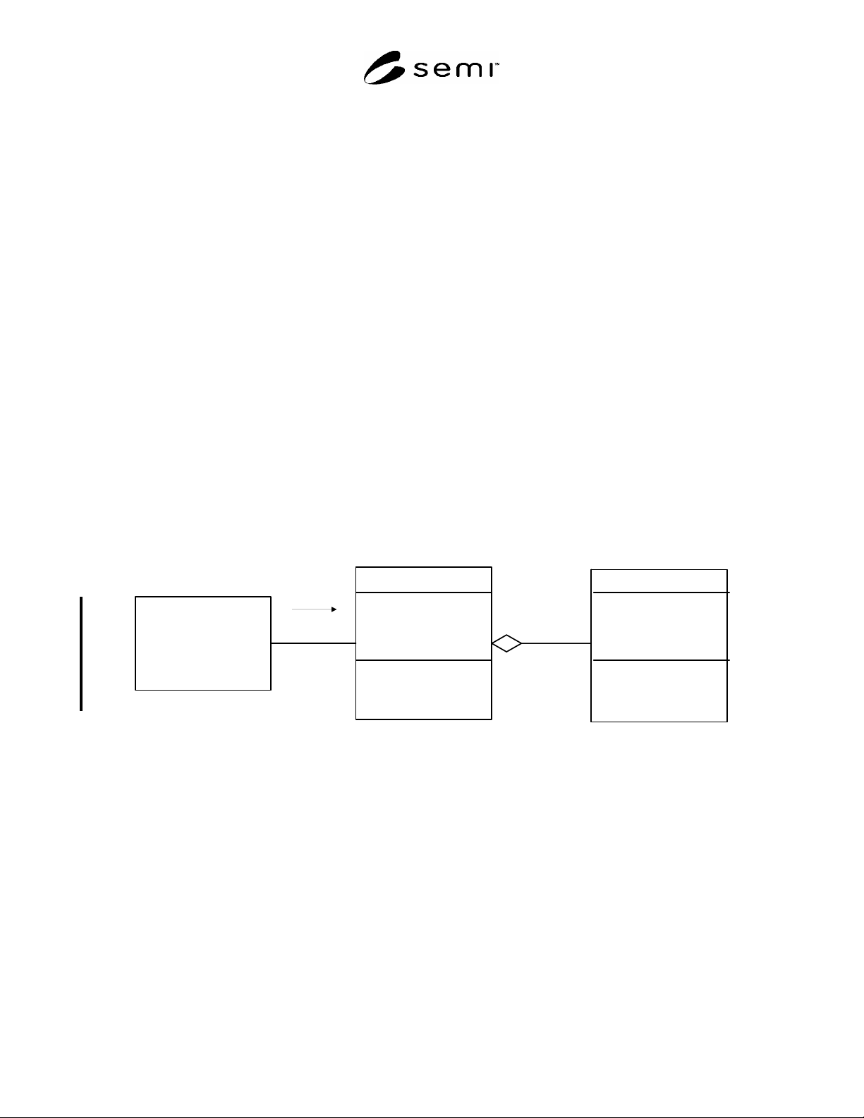
R2-2.1 The object model in Figure R2-1 shows objects for the general (multi-head) WIDR satisfying fundamental
requirements only. It shows the WIDR subsystem as made up of one or more heads. It also illustrates the required
attributes and services provided by the WIDR and its relationships with its upstream controller and with its heads.
1+
WIDR
- Confi
g
uration
- AlarmStatus
- SoftwareRevLevel
- O
p
erationalStatus
Chan
g
eState
Get Attributes
Get Status
H
ead
- HeadAlarmStatus
- HeadID
- HeadStatus
Get Attributes
Get Status
ReadWID
U
p
stream
Controller
requests services
from
is made up of
Figure R2-1
Object Model for Fundamental Requirements
SEMI E118-1104
E
© SEMI 2002, 2004 16
R2-3 Full Capabilities
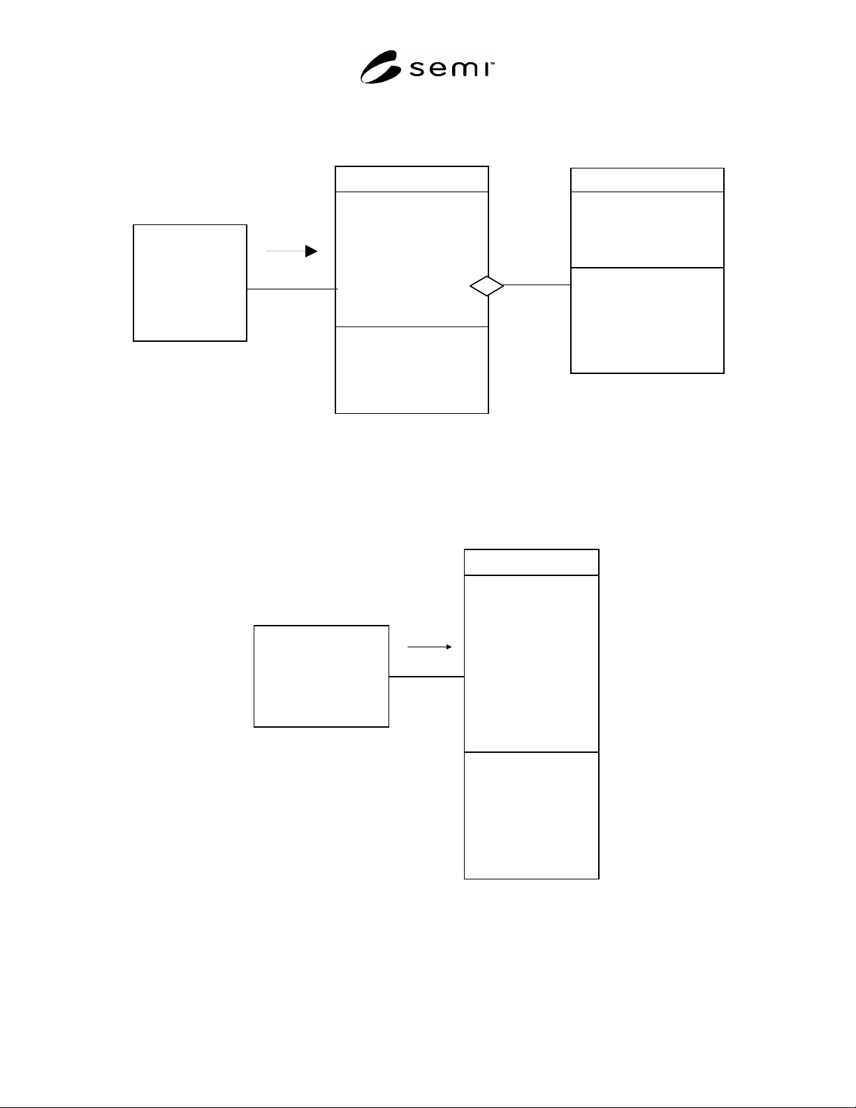
R2-3.1 Figure R2-2 shows the object model for a WIDR with full capabilities, so that all optional attributes and
services are supported.
1+
WIDR
- AlarmStatus
- Configuration
- DateInstalled
- DeviceType
- HardwareRevisionLevel
- MaintenanceData
- Manufacturer
- ModelNumber
- OperationalStatus
- SerialNumber
- SoftwareRevisionLevel
ChangeState
GetAttributes
GetStatus
PerformDiagnostics
Reset
SetAttributes
Head
- HeadAlarmStatus
- HeadDateInstalled
- HeadID
- HeadStatus
- HeadMaintenanceData
Upstream
Controller
requests
services from
is made up of
GetAttributes
GetStatus
ReadWID
ReadWIDC
Figure R2-2
Object Model for Full Capabilities
R2-4 Integrated Model
R2-4.1 Figure R2-3 shows the object model for a WIDR with full capabilities and a single integrated head. The
head is not shown as a separate component in this case, and the head attributes and services have become part of the
WIDR subsystem itself.
WIDR
- AlarmStatus
- Configuration
- DateInstalled
- DeviceType
- HardwareRevisionLevel
- HeadAlarmStatus
- HeadStatus
- MaintenanceData
- Manufacturer
- ModelNumber
- OperationalStatus
- SerialNumber
- SoftwareRevisionLevel
ChangeState
GetAttributes
GetStatus
PerformDiagnostics
ReadWID
Reset
SetAttributes
Upstream
Controller
requests
services from
ReadWIDC
Figure R2-3
Integrated Model with Full Capabilities
SEMI E118-1104
E
© SEMI 2002, 2004 17
RELATED INFORMATION 3
APPLICATION NOTES
NOTE: This related information is not an official part of SEMI E118 and was derived from work of the originating
task force. This related information was approved for publication by full letter balot procedures on July 19, 2002.
R3-1 Combined State Model
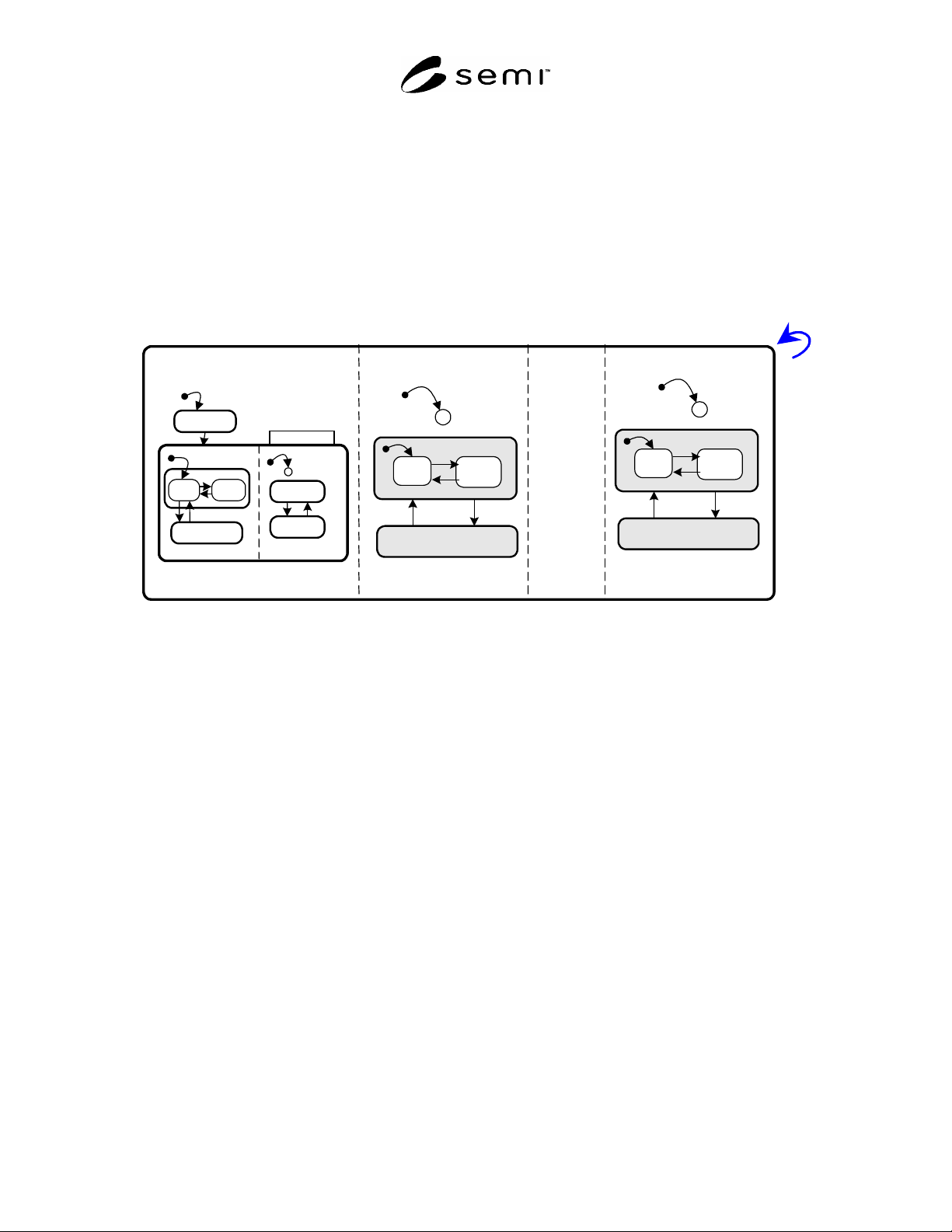
R3-1.1 Figure R3-1 shows the combined state model for the WIDR unit with nn heads, from HEAD01 TO
HEADnn. The WIDR is considered as IDLE when and only when it is in OPERATING and all of its heads are
IDLE.
WIDR
HEAD01
C
12
OPERATING
16
BUSY
IDLE
13
14
15
NOT OPERATING
C
12
HEADnn
11
1
INITIALIZING
3
2
NO
ALARMS
ALARMS
MAINTENANCE
4
5
9
10
ALARM STATUS
OPERATIONAL
RUNNING
IDLE
7
8
6
BUSY
OPERATING
C
OPERATING
16
BUSY
IDLE
13
14
NOT OPERATING
15
.....
Figure R3-1
Combined State Model
NOTICE: SEMI makes no warranties or representations as to the suitability of the standards set forth herein for any
particular application. The determination of the suitability of the standard is solely the responsibility of the user.
Users are cautioned to refer to manufacturer's instructions, product labels, product data sheets, and other relevant
literature, respecting any materials or equipment mentioned herein. These standards are subject to change without
notice.
By publication of this standard, Semiconductor Equipment and Materials International (SEMI) takes no position
respecting the validity of any patent rights or copyrights asserted in connection with any items mentioned in this
standard. Users of this standard are expressly advised that determination of any such patent rights or copyrights, and
the risk of infringement of such rights are entirely their own responsibility.
Copyright by SEMI® (Semiconductor Equipment and Materials
International), 3081 Zanker Road, San Jose, CA 95134. Reproduction of
the contents in whole or in part is forbidden without express written
consent of SEMI.