semi合集-English.pdf - 第590页
SEMI E79-0304 © SEMI 1999, 2004 24 Figure R2-1 Productivity Efficiency Plane NOTICE: SEMI makes no warranties or representations as to the suitability o f the standard set forth herein for any particular application. The…

SEMI E79-0304 © SEMI 1999, 2004 23
Sample Rapid Characterization of Intrinsic Equipment
Efficiency (IEE)
Four experiments were designed and executed with the
following results:
Exp.
Units of Recipe i
Per Experiment
Value-Added
In-Process
Theoretical
Production Time
Per Unit
(VTHT
i
)
Production
Time Per
Experiment
1 50 of recipe A 0.00670 hr/unit 3.3333 hr
2 100 of recipe B 0.00550 hr/unit 5.0000 hr
3 150 of recipe B 0.00550 hr/unit 6.0000 hr
4 300 of recipe A 0.00670 hr/unit 10.0000 hr
Effective Unit Throughput Per Experiment
= (Total Units Per Experiment)
/(Production Time Per Experiment)
Intrinsic Equipment Efficiency (IEE) Per Experiment
= [Σ
i
(Units of Recipe i Per Experiment × VTHT
i
)
/(Production Time Per Experiment)] × 100%
Non-Value-Added Overhead Time Per Experiment
= [(Production Time Per Experiment)
- Σ
i
(Units of Recipe i Per Experiment × VTHT
i
)]
Experiment
Effective
Unit
Throughput
Intrinsic
Equipment
Efficiency
Non-Value-
Added
Time
in Hours
1 15 units/hr 10.05% 2.9983 hr
2 20 units/hr 11.00% 4.4500 hr
3 25 units/hr 13.75% 5.1750 hr
4 30 units/hr 20.10% 7.9900 hr
R2-2 Productivity Efficiency Plane (PEP)
R2-2.1 It is recognized that OEE and throughput are
separate metrics whose relationship may not be
straightforward. Because theoretical production time
per unit may vary widely by recipe, good throughput
performance may not indicate correspondingly good
performance in terms of overall equipment efficiency.
Similarly, a high OEE score may not be indicative of
high throughput. Given this disparity, it is essential that
both metrics be analyzed and compared as separate
entities.
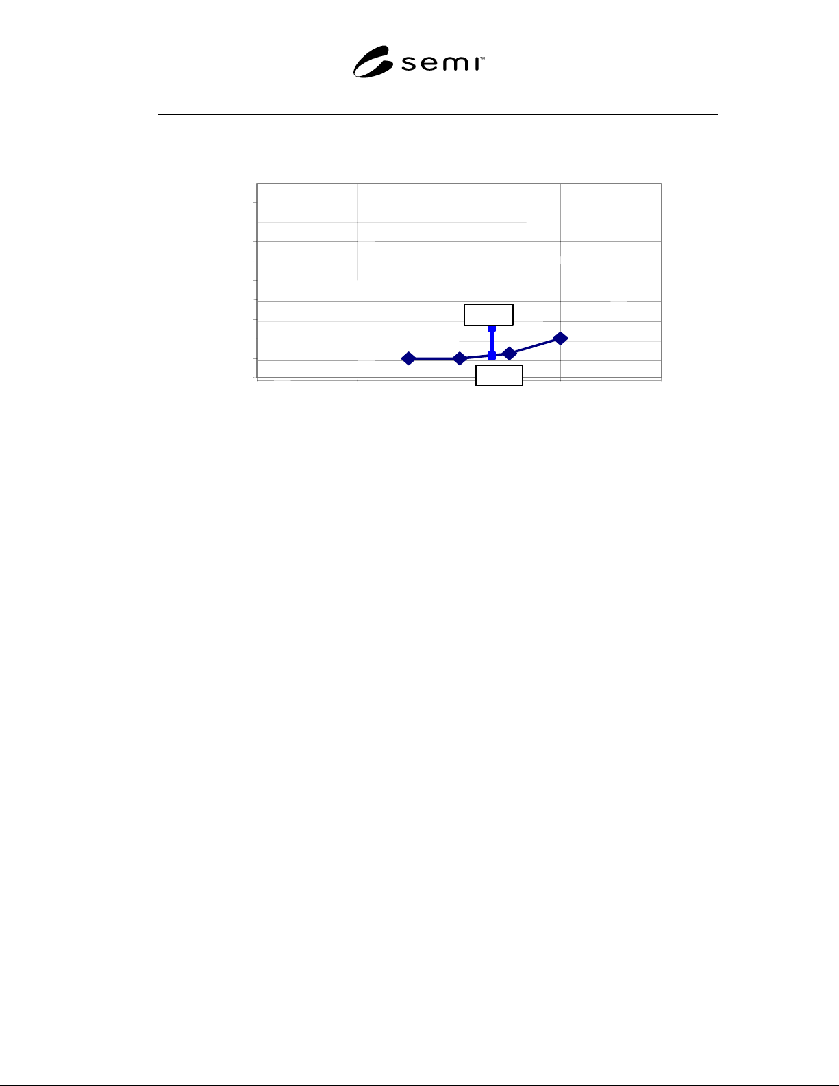
R2-2.2 Data from rapid characterization experiments
may be displayed graphically on a Productivity
Effectiveness Plane (PEP) diagram, Figure R2-1.
R2-2.3 In PEP diagrams, IEE is plotted as a function of
throughput. Points that appear further to the right have
higher throughput and points that appear higher up have
higher IEE. It is desired to have combined equipment
and process designs whose performance would appear
in the upper right quadrant of the plane for the entire
operating range of the tool.
R2-2.4 The four experimental data points from the
sample problem are plotted in Figure R2-1 and, when
connected, appear to approximate an upward sloping
curve. This curve is referred to as a tool signature.
R2-2.5 Tool signatures may be used to describe tool
performance relative to isolated variables. This
representation helps equipment suppliers and users
visualize the effects of tool operating modes on IEE and
throughput. For more complex multi-dimensional
experiment sets, the tool signature would appear as a
hyper-surface.
R2-2.6 OEE can be plotted for comparison against tool
signatures. In Figure R2-1, an OEE measurement of a
typical week is plotted. For the known throughput
corresponding to this OEE score, the value of IEE on
the tool signature for the same throughput may be used
to approximate the IEE score for the week without
calculating IEE explicitly.
SEMI E79-0304 © SEMI 1999, 2004 24
Figure R2-1
Productivity Efficiency Plane
NOTICE: SEMI makes no warranties or
representations as to the suitability of the standard set
forth herein for any particular application. The
determination of the suitability of the standard is solely
the responsibility of the user. Users are cautioned to
refer to manufacturer’s instructions, product labels,
product data sheets, and other relevant literature
respecting any materials mentioned herein. These
standards are subject to change without notice.
The user’s attention is called to the possibility that
compliance with this standard may require use of copy-
righted material or of an invention covered by patent
rights. By publication of this standard, SEMI takes no
position respecting the validity of any patent rights or
copyrights asserted in connection with any item
mentioned in this standard. Users of this standard are
expressly advised that determination of any such patent
rights or copyrights, and the risk of infringement of
such rights, are entirely their own responsibility.
Productivity Efficiency Plane [PEP]
0%
10%
20%
30%
40%
50%
60%
70%
80%
90%
100%
010203040
Effective Unit Throughput (uph)
IEE
and
OEE
(%)
OEE
IEE
Copyright by SEMI® (Semiconductor Equipment and Materials
International), 3081 Zanker Road, San Jose, CA 95134. Reproduction o
f
the contents in whole or in part is forbidden without express written
consent of SEMI.

SEMI E80-0299 (Reapproved 1104)
TEST METHOD FOR DETERMINING ATTITUDE SENSITIVITY OF MASS
FLOW CONTROLLERS (MOUNTING POSITION)
This test method was technically approved by the Global Gases Committee and is the direct responsibility of
the North American Gases Committee. Current edition approved by the North American Regional Standards
Committee on July 11, 2004. Initially available at www.semi.org September 2004; to be published
November 2004. Originally published in 1999; last published November 2004.
1 Purpose
1.1 The purpose of this test method is to provide a
standardized method for quantifying the effect of
mounting attitude on an MFC.
1.2 This document provides a common basis for
communication between manufacturers and users
regarding testing and describing MFC mounting effects.
2 Scope
2.1 This procedure describes a method to determine the
effect of attitude (mounting position) of a Mass Flow
Controller on flow span and zero.
2.2 The intent of this document is not to suggest any
specific testing program but to specify the test method
to be used when testing for parameters covered by this
method. Reference operating conditions represent the
environmental conditions where the "best" performance
can be expected.
2.3 The minimum test described in this document is to
test one MFC in 5 common mounting positions using
Nitrogen gas at 135.8 kPa (19.7 psia) and 308 kPa (44.7
psia). This test method can be used to evaluate
additional gases, pressures or mounting attitudes.
NOTICE: This standard does not purport to address
safety issues, if any, associated with its use. It is the
responsibility of the users of this standard to establish
appropriate safety and health practices and determine
the applicability of regulatory or other limitations prior
to use.
3 Limitations
3.1 It is not practical to evaluate performance under all
possible combinations of operating conditions. This test
procedure should be applied under laboratory
(reference) conditions; its intent is to collect sufficient
data to form a judgment of the field performance of the
MFC being tested.
3.2 The results from this test represent the performance
of the specific device tested i.e., make, model, full scale
flow and operating conditions. The results may not
apply to devices of different manufacture, model, full
scale flow or under different operating conditions.
3.3 Due to manufacturing variability, attitude
sensitivity may vary for the same model of MFC. To
statistically quantify attitude sensitivity for a particular
model of MFC, multiple samples should be tested.
4 Referenced Standards
None.
5 Terminology
5.1 Acronyms and Abbreviations
5.1.1 % F.S. — Percent Full Scale
5.1.2 DUT — Device Under Test
5.1.3 HBD — Horizontal Base Down. Mounting attitude
1, as shown in Figure 1.
5.1.4 HED — Horizontal Either side Down. Mounting
attitude 3, as shown in Figure 1.
5.1.5 HUD — Horizontal Upside Down. Mounting
attitude 5, as shown in Figure 1.
5.1.6 kPa — KiloPascal
5.1.7 MFC — Mass Flow Controller
5.1.8 psia
Pounds per Square Inch Absolute
5.1.9 SAS
max
the maximum Span Attitude
Sensitivity between two attitudes
5.1.10 SAS
nm
Span Attitude Sensitivity between
attitudes n and m
5.1.11 Sccm — Standard cubic centimeters per minute
5.1.12 Slm — Standard liters per minute
5.1.13 VFD — Vertical Flow Down. Mounting attitude
2, as shown in Figure 1.
5.1.14 VFU — Vertical Flow Up. Mounting attitude 4,
as shown in Figure 1.
5.1.15 VID — Vertical Inlet Down. Mounting attitude 4,
as shown in Figure 1.
5.1.16 VIU — Vertical Inlet Up. Mounting attitude 2, as
shown in Figure 1.
SEMI E80-0299 © SEMI 1999, 2004 1