semi合集-English.pdf - 第4051页
SEMI F53-0600 © SEMI 2000 8 Any Malfunctions End of Radiated Testing Initiate Conducted Testing Set Up Apparatus Spike on "+" DC Lead Tests A. Increase Spike Amplitude and Record Data B. Is MFC Digital C. Hold …
SEMI F53-0600 © SEMI 20007
14.1.7.1 Where reference conditions are defined by
50% FS flow with the EMI source at zero field strength.
14.1.8 Record these values in Table 2.
14.2 Interpretation of Results
14.2.1 The changes in flow columns in Table 2 give an
indication of the effect of EM susceptibility, both
radiated and conducted. If the effect is larger than can
be tolerated for the process in the fab, two steps may be
necessary. EM field strength and frequency
measurements should be made at the fab under normal
operating conditions. If EM measurements in the fab
match areas that cause unacceptable effects on the
MFC, shielding may be necessary to reduce the effect.
Shielding design is beyond the scope of this test
method.
15 Illustrations
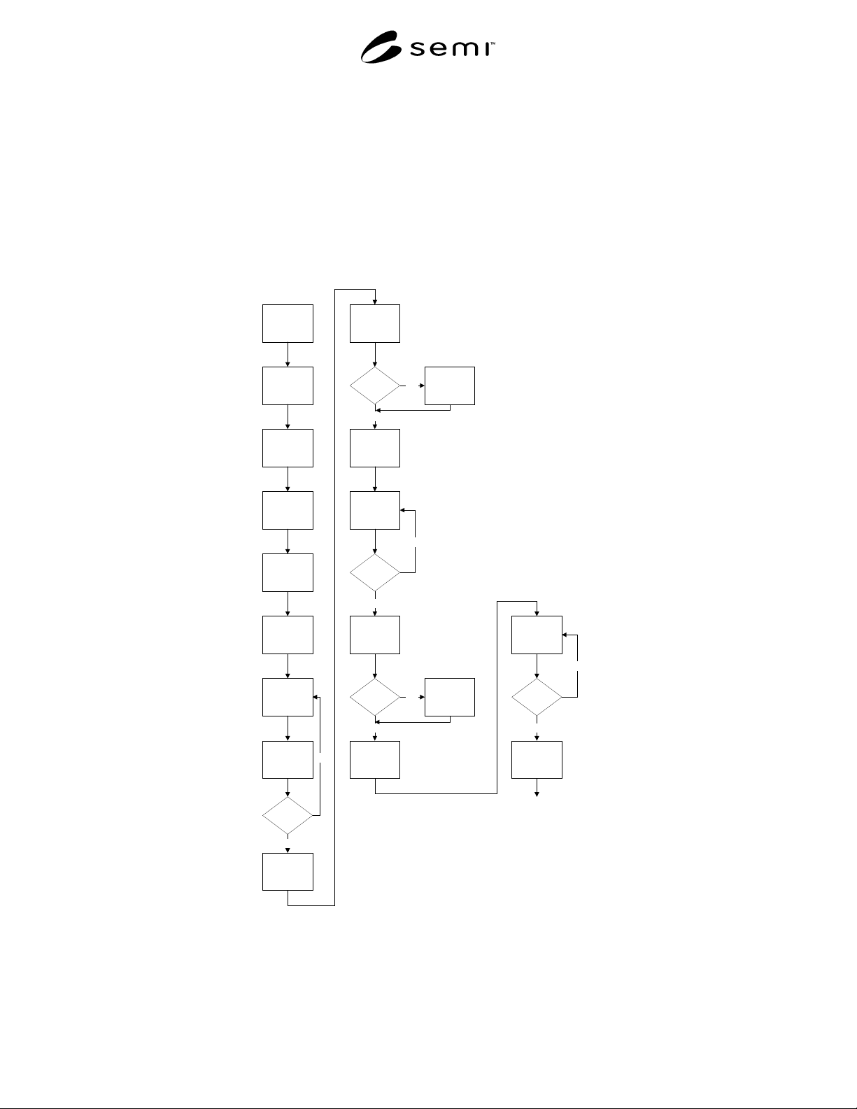
Start
Set up Test
Apply Power
Allow Warm
Up
Purge With N2
Zero MFC and
Record Data
Set Up 50%
Flow of N2 and
Record Data
Initiate
Radiated EM
Testing
Set Frequency
and Record
Data
Repeat Until all
Frequencies
are Covered
Are all
Frequencies
Tested
Set Up for High
Frequency
Sweep
Frequency 50
KHz to 20 MHz
Any
Malfunctions
Locate
Frequency of
Malfunction
and Record
Set Up for
Higher
Frequencies
Set Frequency
and Record
Data
Are all
Frequencies
Tested
Sweep
Frequency 30
MHz to 200
MHz
Any
Malfunctions
Locate
Frequency of
Malfunction
and Record
Set Up for High
Frequency
Set Frequency
and record
Data
Are All
Frequencies
Tested
Sweep
Frequencu 300
MHz to 990
MHz
Yes
No
Yes
No
No
Yes
Yes
No
No
Yes
Figure 1
Flow Chart of Test Method
SEMI F53-0600 © SEMI 2000 8
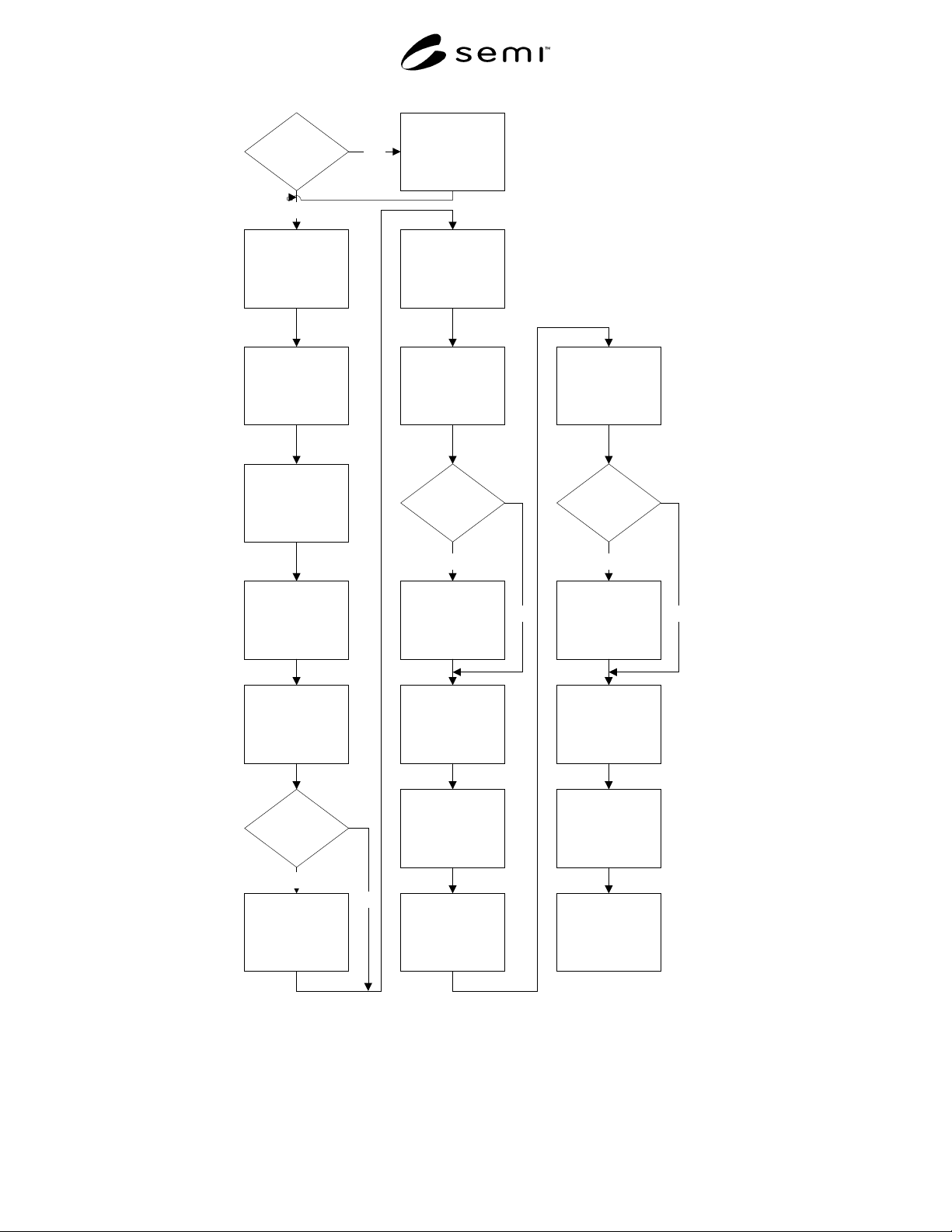
Any
Malfunctions
End of Radiated
Testing
Initiate Conducted
Testing
Set Up Apparatus
Spike on "+" DC
Lead Tests
A.
Increase Spike
Amplitude and
Record Data
B.
Is MFC Digital
C.
Hold at Highest
Level for 5 Minutes
Locate Frequency
of Malfunction and
Record
D.
Spike on "+" DC
Lead
E.
Increase Spike
Amplitude and
Record Data
G.
Hold at Highest
Level for 5 Minutes
F.
Is MFC Digital
Spike on "-" DC
Lead
Repeat steps A-G
Spike on Control
Lead
H.
Apply Full Scale
Control Signal and
Increase Spike,
Record Data
J.
Hold at Highest
Level for 5 Minutes
I.
If Not Susceptible
and Digital
Apply Negative
Spike on Control
Leads
Repeat Steps H-J
End Test
Yes
No
Yes
No
Yes
No
Yes
No
Figure 1 (continued)
Flow Chart of Test Method
SEMI F53-0600 © SEMI 20009
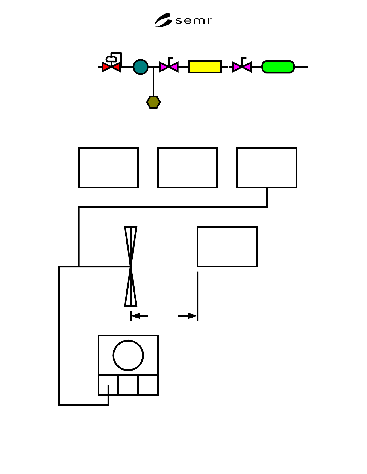
N2 Source
Regulator
Heat
Exchanger
Inlet
Valve
Outlet
Valve
MFC
Flow Standard
Gas
Temperature
Figure 2
MFC Test Setup
Computer Controller Signal Generator
Power Amplifier
(See NOTE 1.)
Equipment Under Test
A
ntenna (See NOTE 2.)
1M
Oscilloscope
A
NOTE 1: Change Power Amp as Required.
NOTE 2: Change Antenna as Required.
Figure 3
Radiated Electric Field Susceptibility Test Setup