semi合集-English.pdf - 第3642页
SEMI E142-0705 © SEMI 2005 4 MapData BinDefin ition BinCode DeviceIdMap Transfer TransferMap DeviceId BinCodeMap AliasId Overlay ReferenceDevice Substrate SubstrateMap Layout SubstrateMaps Overlays Aliases ReferenceDevic…
SEMI E142-0705 © SEMI 2005 3
7.3.3 Service Message Definition
7.3.3.1 A service message definition table defines the parameters used in a service, as shown in the following table:
Parameter Req/Ind Rsp/Cnf Comment
7.3.3.2 The columns labeled REQ/IND and RSP/CNF link the parameters to the direction of the message. The
message sent by the initiator is called the “Request”. The receiver terms this message the “Indication” or the request.
The receiver may then send a “Response” which the original sender terms the “Confirmation”.
7.3.3.3 The following codes appear in the REQ/IND and RSP/CNF columns and are used in the definition of the
parameters (eg., how each parameter is used in each direction):
M Mandatory Parameter — Must be given a valid value.
C Conditional Parameter — May be defined in some circumstances and undefined in others. Whether a value is given
may be completely optional or may depend on the value of the other parameter.
U User-Defined Parameter.
- The parameter is not used.
= (For response only.) Indicates that the value of this parameter in the response must match that in the primary (if
defined).
8 Overview
8.1 Substrate maps are two dimensional arrays of data that correspond to a physical substrate which may be a wafer,
strip or tray as shown in the Appendices. It is expected that other substrate types will be added to subsequent
releases of this standard.
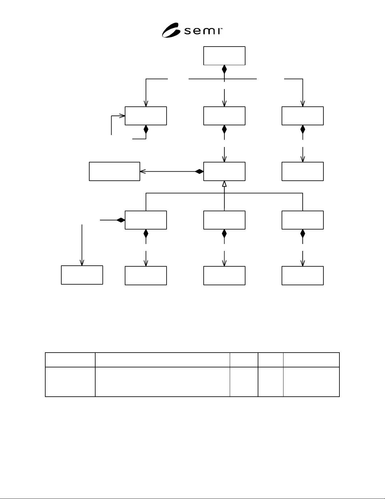
8.2 The data items are defined as attributes of the objects shown in Figure 1 Map Data Object Model.
SEMI E142-0705 © SEMI 2005 4
MapData
BinDefinition
BinCode
DeviceIdMap
Transfer
TransferMap
DeviceId
BinCodeMap
AliasIdOverlayReferenceDevice
SubstrateSubstrateMapLayout
SubstrateMaps
Overlays Aliases
ReferenceDevices
DeviceIds TransfersBinCodes
ChildLayout
BinDefinitions
Layouts Substrates
1
0..*
1..*
1..*
1..*
1..*
0..* 0..*
1
1
1
0..*
0..* 1
11 1
1
0..*
0..*
Figure 1
Map Data Object Model
9 MapData
9.1 The MapData object contains a list of zero or more Layout objects, a list of zero or more SubstrateMap objects
and a list of zero or more Substrate objects.
Table 1 MapData Attributes
Attribute Name Definition Access Reqd Form
FormatRevision Specifies the exact name and revision of the format used
to represent substrate map data. This field can be used by
a parser to automatically determine the format of the
remaining substrate map data.
RO N Text
10 Layout
10.1 The Layout object defines the logical and physical dimensions of two-dimensional array of devices to which a
SubstrateMap may be assigned. A substrate must have a top level layout that defines the size of the substrate itself.
Any layout object can reference other child layout objects. In this way complex assemblies may be represented.
See the examples in Related Information 1.
SEMI E142-0705 © SEMI 2005 5
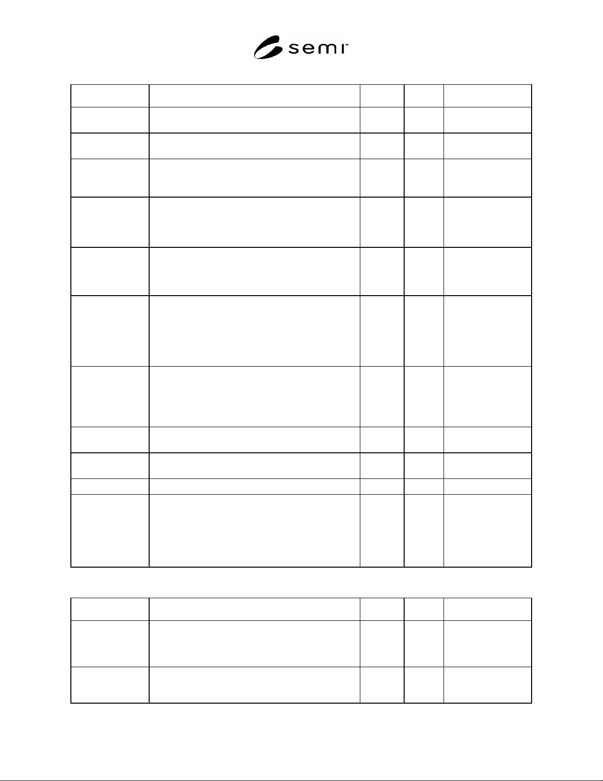
Table 2 Layout Attributes
Attribute Name Definition Access Reqd Form
LayoutId The layout identifier. This must be unique within the
scope of MapData.
RO Y Text
DefaultUnits The units in which physical dimensions and coordinates
are represented unless otherwise specified.
RO Y Text
Dimension The number of columns (X-axis) and rows (Y-axis) in the
layout.
If this is the top level layout then X = 1, Y = 1.
RO Y LogicalCoordinates
(see Table 3)
DeviceSize The X and Y dimensions of the device.
If this is the top level layout, then this defines the size of
the substrate itself.
If not present, then DeviceSize is not defined.
RO N XYDimensions
(see Table 4)
StepSize The distance from a reference point on one device to the
same reference point on the adjacent device. StepSize –
DeviceSize is equal to the “street” width between devices.
If not present, then StepSize is not defined.
RO N XYDimensions
(see Table 4)
LowerLeft The distance in microns of the lower left corner of this
layout from the lower left corner of the parent layout.
If this is the top level layout, then LowerLeft.X = 0 and
LowerLeft.X = 0.
If not present, then LowerLeft.X = 0 and LowerLeft.X =
0.
RO N XYDimensions
(see Table 4)
Z The logical and physical height of the device above (or
below) the parent layout.
If this is the top level layout, then Z.Order = 0 and
Z.Height = 0.
If not present, then Z.Order = 0 and Z.Height = 0.
RO N ZDimensions
(see Table 5)
TopImage Name of an image file showing the top side of an
individual device in the layout.
RO N Text
BottomImage Name of an image file showing the bottom side of an
individual device in the layout.
RO N Text
ProductId Product identifier for a device in this layout. RO N Text
TopLevel TopLevel = True implies that this is a top level layout.
TopLevel = False implies that this layout is the child of
another layout.
If this is the top level layout, then TopLevel = True.
If not present, then TopLevel = False. TopLevel may be
omitted from child layouts.
RO N Boolean
Table 3 LogicalCoordinates Type
Attribute Name Definition Access Reqd Form
X The column or X logical coordinate, according to the
values of SubstrateMap coordinate attributes;
SubstrateSide, Orientation, OriginLocation, and
AxisDirection.
RO Y Integer
Y The row or Y logical coordinate, according to the values
of SubstrateMap coordinate attributes; SubstrateSide,
Orientation, OriginLocation, and AxisDirection.
RO Y Integer