semi合集-English.pdf - 第1507页
SEMI E32-0997 © SEMI 1994 , 1997 2 Table 4.2 Atomic Tr ansfer State Transition Table Table 4.3 Extended Transfer Job State Transition Tabl e Table 4.4 Ex tended Atomic Transfer State Transition T able Table 4.5 Equipment…

SEMI E32-0997 © SEMI 1994, 19971
SEMI E32-0997
MATERIAL MOVEMENT MANAGEMENT (MMM)
CONTENTS
1 Introduction
1.1 Purpose
1.2 Scope
1.3 References
1.4 Conventions
1.4.1 State Models
1.4.2 Object Services
2 Definitions
3 Overview
3.1 Macro and Micro Levels
3.2 Ports and Locations
3.3 Compliance
4 Macro Level
4.1 Macro Level Concepts
4.1.1 Macro Level Definitions
4.1.2 Atomic Transfer
4.1.3 Compound Transfer
4.1.4 Parallel Transfers
4.1.5 Transfer Recipe
4.1.6 Transfer System Controller as Transfer
Agent
4.1.7 Transfer Job
4.2 Macro Level Behavior
4.2.1 Macro Level Communications
4.2.2 Transfer Job State Model
4.2.3 Atomic Transfer State Model
4.3 Extended Behavior Models
4.3.1 Extended Communications
4.3.2 Extended Transfer Job State Model
4.3.3 Extended Atomic Transfer State Model
4.4 Macro Level Services
4.4.1 Service List
4.4.2 Service Detail
4.4.3 Parameter/Attribute Definitions
4.5 Object Attribute Definitions
4.5.1 Equipment
4.5.2 TransferJob Object
4.5.3 AtomicTransfer Object
5 Micro Level
5.1 Micro Level Concepts
5.1.1 Micro Level Definitions
5.1.2 Micro Level Description
5.2 Micro Level Behavior
5.2.1 Micro Level Communications
5.2.2 Micro Level Messaging via Host
5.3 Extended Behavior
5.4 Micro Level Services
5.4.1 Service List
5.4.2 Service Detail
5.4.3 Parameter Definitions
Application Notes
A1-1 Transfer-Related Mechanisms
A1-1.1 Example Port State Model
A1-1.2 Additional Related Mechanisms
A1-2 WIP Tracking
A1-3 Error Handling
A1-3.1 Macro Level Error Handling
A1-3.2 Micro Level Error Handling
A1-4 Practical Applications
A1-4.1 Passive Transfer
A1-4.2 Active Transfer/Exchange of Cassettes
A1-4.3 Sequential Moves
A1-4.4 Linked Lithography
A1-4.5 Non-Compliant Transfer Partner
Index
List of Tables
Table 4.1 Transfer Job State Transition Table

SEMI E32-0997 © SEMI 1994, 1997 2
Table 4.2 Atomic Transfer State Transition Table
Table 4.3 Extended Transfer Job State Transition
Table
Table 4.4 Extended Atomic Transfer State
Transition Table
Table 4.5 Equipment Object Definition Table
Table 4.6 TransferJob Object Definition Table
Table 4.7 AtomicTransfer Object Definition Table
Table A1-1 Extended Atomic Transfer State
Transition Table
List of Figures
Figure 1.1 Illustration of Material Movement
Scope
Figure 3.1 Port vs. Location
Figure 4.1 Transfer Job Sequencing
Figure 4.2 Macro Level Message Flow
Figure 4.3 Macro Level Messaging With Events
Figure 4.4 Transfer Job State Diagram for a Single
Port
Figure 4.5 Transfer Job State Model for Multiple
Ports
Figure 4.6 Atomic Transfer State Diagram
Figure 4.7 Extended Transfer Job State Model
Figure 4.8 Extended Atomic Transfer State
Diagram
Figure 5.1 Micro Level Message Flow
Figure 5.2 Micro Level Message Flow via Host
Figure A1-1 Example Port State Diagram
SEMI E32-0997 © SEMI 1994, 19973
SEMI E32-0997
MATERIAL MOVEMENT MANAGEMENT (MMM)
1 Introduction
Automated material movement represents a significant
milestone in the evolution of automation in
semiconductor manufacturing. The standardization of
the transfer process is critical to the economic viability
of material movement automation. This standard
addresses the communications needs of the
semiconductor manufacturing facility with respect to
material movement.
1.1 Purpose — This standard addresses automated
material movement on the semiconductor factory
floor—the task of transporting objects (material, et al)
from one processing or storage location to another. It
defines the concepts of material movement, the
behavior of the equipment (including transfer devices)
in relation to material movement, and the messaging
services which are needed to accomplish the task.
1.2 Scope — The scope of this standard is defined
from two viewpoints. The first is the breadth of the
functionality covered. The second is the depth to which
it is covered.
The breadth of functionality covered by this standard is
limited to the activity required to transfer an object
from a location on entity “A” to a location on entity
“B” under the supervision of a factory host. This
transfer may occur directly between two factory process
equipment, or may involve the assistance of a “transfer
agent”, a device dedicated to material transfer. Thus,
the material movement domain includes a maximum of
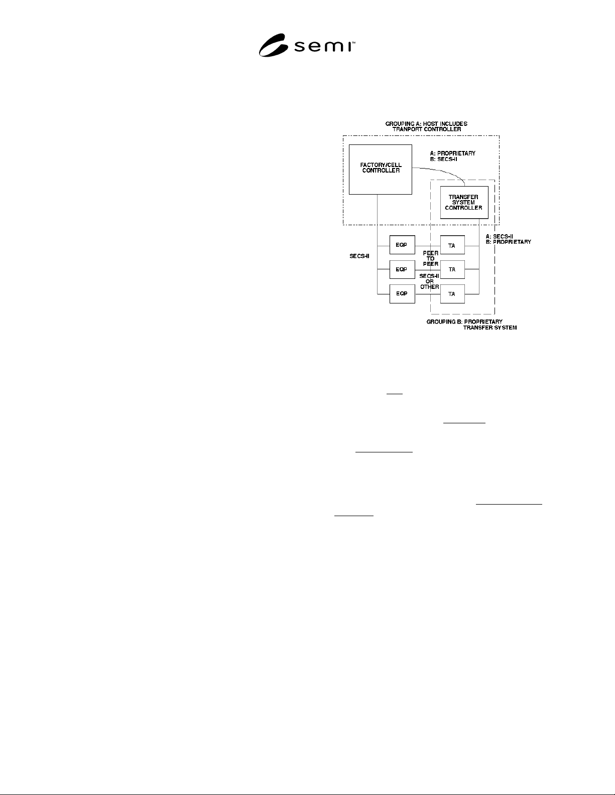
four types of entities (see Figure 1.1):
Figure 1.1
Illustration of Material Movement Scope
1. The factory host, which might, for example, be a
factory controller or cell controller.
2. The set of process-related equipment, to which the
host communicates.
3. The transfer agent, which performs the physical
transport of the material in the factory. The transfer
agent might communicate directly with the host or
be controlled by an intermediate system.
4. This intermediate system, the transfer system
controller, is the fourth type of entity.
This document assumes that the transfer system
controller is either a part of the host or a part of a
potentially complex transfer agent (as shown by the
dotted boxes in Figure 1.1). Thus, the term “transfer
system controller” seldom appears. The case where a
“transfer agent” is actually a transfer system controller
plus multiple transport devices is discussed further in
Section 4.1.6.
There are some forms of material movement that do not
fall within the domain of this standard and thus are not
applicable to the methods described below. One
example might be a non-deterministic system, such as a
conveyer where generic parts are placed onto the
system and circle until randomly selected by a
workstation needing that type of part.