semi合集-English.pdf - 第4282页
SEMI F80-1103 © SEMI 2003 2 7.1.5 Open APV2 an d flow Gas B from the Purge line. When flowing, close APV3 and fill the line with Gas B up to PV2. Then, close PV2. Gas B also fills the line downstr eam of PV2. Open APV3, …

SEMI F80-1103 © SEMI 2003 1
SEMI F80-1103
TEST METHOD FOR DETERMINATION OF GAS CHANGE/PURGE
EFFICIENCY OF GAS DELIVERY SYSTEM
This test method was technically approved by the Global Facilities Committee and is the direct responsibility
of the Japanese Facilities Committee. Current edition approved by the Japanese Regional Standards
Committee on August 8, 2003. Initially available at www.semi.org October 2003; to be published November
2003.
1 Purpose
1.1 This document is a guide to a test method to
determine gas change/purge efficiency of gas delivery
system.
2 Scope
2.1 It covers both conventional metal face sealing and
surface mount gas delivery systems.
2.2 The test method applies to all type of high purity
gas delivery systems used in semiconductor
manufacturing facilities and comparable research and
development areas.
NOTICE: This standard does not purport to address
safety issues, if any, associated with its use. It is the
responsibility of the users of this standard to establish
appropriate safety and health practices and determine
the applicability of regulatory or other limitations prior
to use.
3 Limitations
3.1 All components must meet quality requirements as
established and controlled by manufacturers prior to
testing (e.g., dimensional, functional, etc.).
3.2 Care should be exercised in handling of
components to maintain manufacturer’s specifications.
4 Referenced Standards
None.
5 Terminology
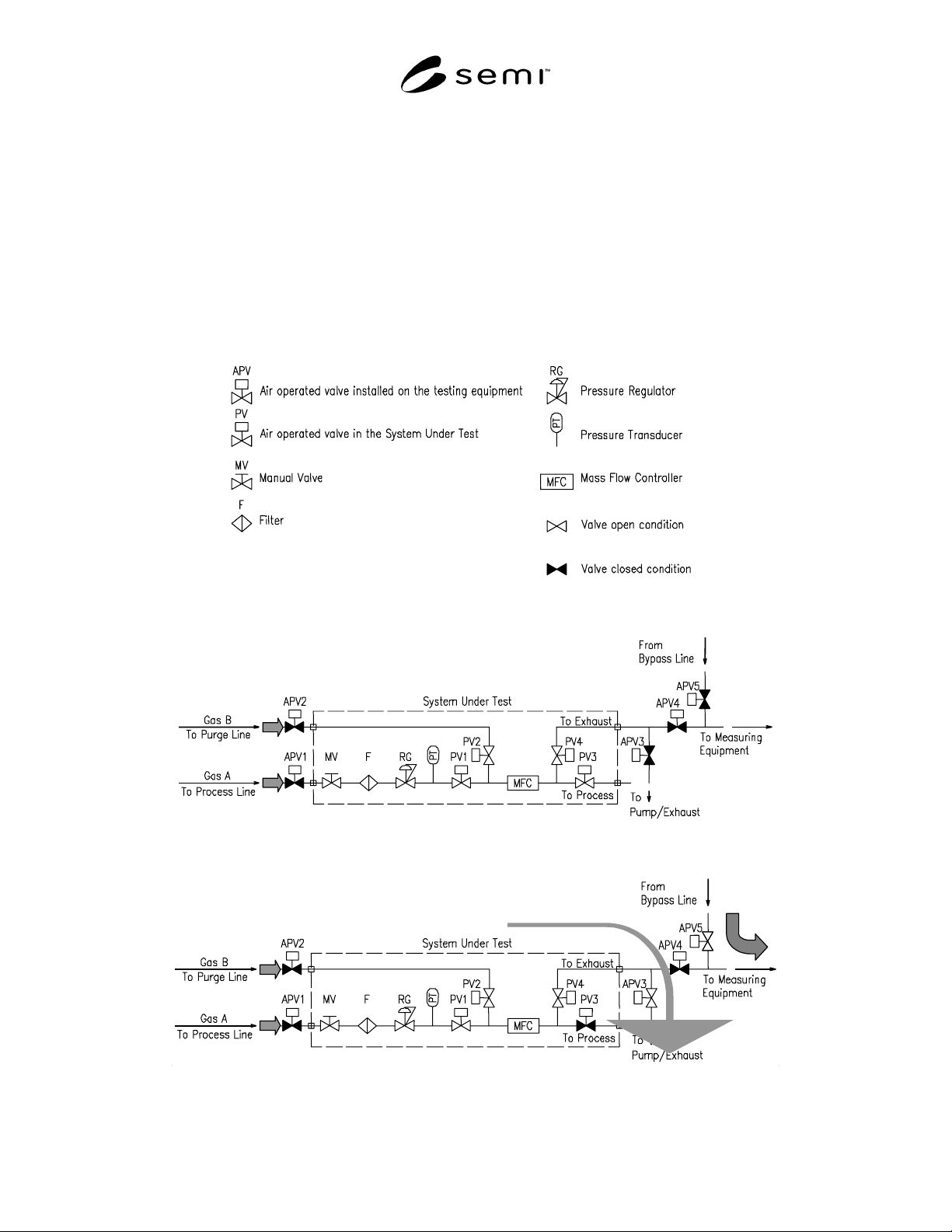
5.1 Abbreviations and Acronyms (See Figure 1.)
5.1.1 APIMS — Atmospheric Pressure Ionization Mass
Spectrometer
5.2 Definitions
5.2.1 purge efficiency — the ratio of process gas
concentration before and after the purge event.
5.2.2 required concentration — a concentration that a
user of the gas delivery system required.
6 Condition
6.1 Test shall be performed at 22° C ± 4° C.
6.2 Test gas shall be used for measuring equipment and
shall not be adsorptive gas. Two gases shall be used as
the test gases. They are indicated as Gas A and Gas B
in this test method.
6.3 APIMS or measuring equipment that has a low
detectable limit and has a good response capability of
gas densitometer.
NOTE 1: APIMS is widely used for this type of
measurement.
NOTE 2: Qmass is not considered as a recommended option
as the following reasons; (1) Special sampling valve needs to
be installed on the testing equipment. (2) Detectable limit of
Qmass is high.
NOTE 3: An oximeter is not considered as a recommended
option because it does not have enough capability of response.
6.4 Flow rate of each gas for this test shall be
determined by a mass flow controller of the System
Under Test and a capability of the measuring
equipment.
7 Procedure
7.1 Case (1) — This is the test method in consideration
of purge line in the gas delivery system.
7.1.1 A recommended test flow schematic is shown in
Figure 2.
7.1.2 The test is to evaluate a purge efficiency of gas
delivery systems by using its process line and purge
line.
7.1.3 Set each component for the following condition
before starting the test. APV1, APV2, APV3, APV4,
and APV5 are closed condition. Rest of the components
in the System Under Test are open condition. Supply
Gas A to the upstream of APV1. Supply Gas B to the
upstream of APV2. (See Figure 2.)
7.1.4 Open APV5 and flow Gas A from Bypass line.
(1) Close PV3, open APV3, and vacuum the System
Under Test. (2) (See Figure 3.)
SEMI F80-1103 © SEMI 2003 2
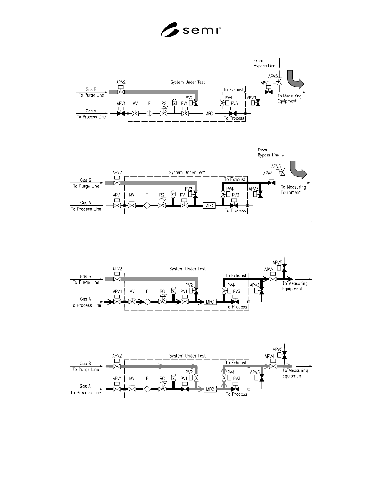
7.1.5 Open APV2 and flow Gas B from the Purge line. When flowing, close APV3 and fill the line with Gas B up
to PV2. Then, close PV2. Gas B also fills the line downstream of PV2. Open APV3, vacuum inside of the line, and
vent Gas B. Then, close APV3. (3) (See Figure 4.)
7.1.6 (a) Open APV1 and flow Gas A from the Process line. (b) Close PV1, open APV3 and vacuum the process
line. Then, Close APV3, open and close PV1, and open APV3. (c) Repeat this operation (b) 3 times and close APV3
to sufficiently fill process line with Gas A. (4) (See Figure 5.)
7.1.7 Close APV5. Then open APV4 and flow Gas A to the System Under Test. Measure the concentration of Gas
A by measuring equipment. (See Figure 6.)
7.1.8 Close PV1, open PV2 and flow Gas B to the System Under Test. The measuring equipment continuously
monitors the Gas A concentration. Record the time to achieve required concentration for Gas A from the start of
flowing Gas B. (See Figure 7.)
Figure 1
Abbreviations and Symbols
Figure 2
Gas Change/Purge Efficiency Test Schematic Case 1
(1)
(2)
Figure 3
Procedure 7.1.4
SEMI F80-1103 © SEMI 2003 3
(3)
Figure 4
Procedure 7.1.5
(4)
Figure 5
Procedure 7.1.6
Figure 6
Procedure 7.1.7
Figure 7
Procedure 7.1.8