semi合集-English.pdf - 第1620页
SEMI E38-1296 © SEMI 1995 , 1996 9 • process m odule (PM)— prov ides manuf ac turing value to material • transport module (TM) — transfers material withi n cluster • cassette module (CM) — e xchanges material with factor…
SEMI E38-1296 © SEMI 1995, 1996 8
Figure 4
Object Designation
In addition to OMT conventions (see Section 5.2), each
object in the information models has one of three
designations: service objects with standardized
attributes (thick border); other objects described in the
sub-section (medium border); and objects described in
other subsections but included to show significant
relationships (thin border).
The models are process- and configuration-independent
and do not dictate the internal architecture of the
controlled modules beyond the physical requirements of
cluster tools.
The first two models show major entities of the
processing equipment and material being processed.
Subsequent models are oriented towards one of the
major functional domains.
7.1.1 Cluster Tool Module Model — The fundamental
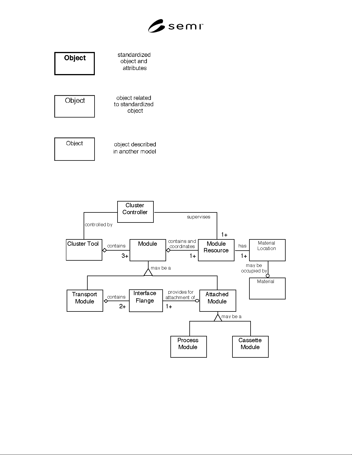
component of a cluster tool is the module. Figure 5
shows that there are three module types within a cluster
tool:
Figure 5
Cluster Tool Module Information Model
SEMI E38-1296 © SEMI 1995, 19969
• process module (PM)— provides manufacturing
value to material
• transport module (TM) — transfers material within
cluster
• cassette module (CM) — exchanges material with
factory
A cluster tool must contain one or more of each of these
module types, as each performs a critical function in the
cluster tool mission. Any module can contain
processing resources.
Supervisory control within the cluster tool is the
responsibility of the cluster controller. The cluster
controller achieves this by supervising the various
module resources using the standard communications
services. It is the primary service-user in the cluster
tool. The form of the cluster controller is not specified
in this standard. It may be a single platform, distributed,
or incorporated with one or more modules.
A module contains and coordinates a number of module
resources dedicated to fulfilling a particular control
function. Each module resource contains at least one
material location, which may or may not contain
material. Note that the location for material processing
is defined separately from the location where the
material is received or sent. This may be virtual if they
are physically the same position, but they cannot be
assumed to be so as this would exclude certain
architectures.
The purpose of each type of module is described in
detail below.
Cassette Module — The component of a cluster used to
interface the cluster to the rest of the factory. It
provides material input and output for the cluster. It
makes only one material at a time available to the
cluster transport (the intratool environment), regardless
of how the material enters the cassette module from
outside the cluster (the intertool environment). It is a
specialization of attached module (AM).
Process Module — A process module is any component
within a cluster which provides one or more steps of
material processing for the cluster system. Material
enters the process module through an interface flange,
undergoes some transformation, and exits through the
same or another interface flange. It is also a
specialization of attached module (AM).
Transport Module — The transport module is
responsible for transfer of material from one cluster-
attached module to another. It consists of a robotic
handler capable of exchanging material with each of the
attached modules at the interface flanges. It can be a
variety of physical topologies (radial or linear, for
example). In SEMI standard cluster tools, the transport
module has an interface isolation valve at each point of
attachment to the attached modules. The transport
module is responsible for managing constraints on the
simultaneous opening of isolation valves as it relates to
contamination of the transport module's environment by
that of an attached module, as well as cross
contamination between attached modules.
The attributes of modules and related objects in Figure
5 are not standardized as these objects are equipment
and process-dependent.
7.1.2 Material Model — Material is received from the
factory, in a carrier or singly, at an intertool port
resource. They are transported within the cluster and
processed by processing resources. Once processed,
they are returned to the factory at the same, or another,
intertool port resource.
The processing which is to be performed on material is
determined from the process specification for that
material.
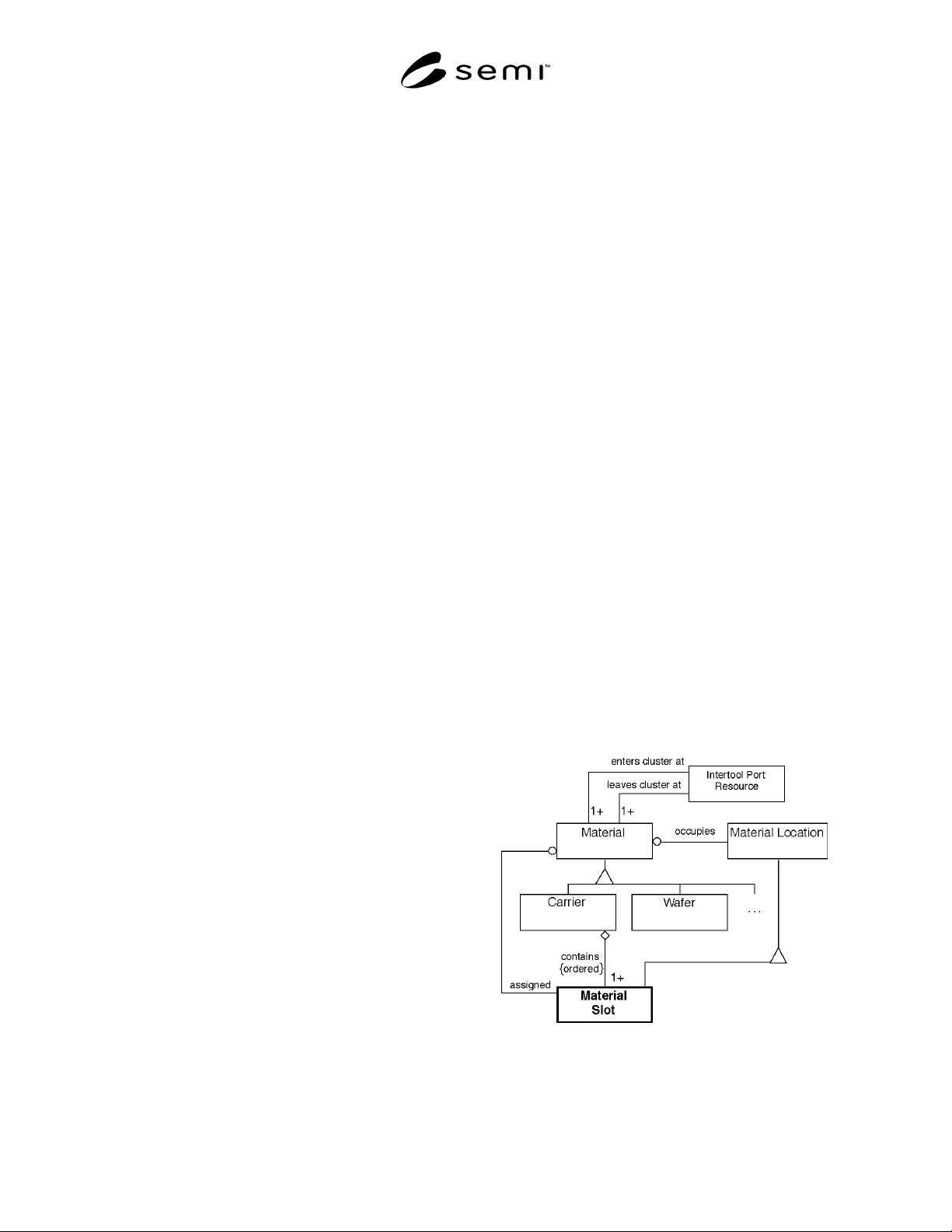
The material model in Figure 6 establishes the
relationships between the material and material
locations. Two material types are of interest in cluster
tool module communications, single material and
carriers. Single material may be grouped in carriers.
This is modeled by defining the material slot object,
which is a type of material location. A carrier is made
up of an ordered set of material slots. A single material
occupies a material slot when in the carrier. In addition,
a single material may be assigned a particular material
slot which it does not yet occupy, indicating that it is to
be received into that material slot when it arrives.
Figure 6
Material Information Model
SEMI E38-1296 © SEMI 1995, 1996 10
Carriers may be cassettes used to transport single material in the factory and to input single material to the cluster
tool, or they may be material boats in batch process modules.
The attributes of the material slot object are standardized to enable mapping of single material in carriers. Other
objects in the diagram are not standardized. However, the identifier of the material, MaterialID, is an attribute of the
material slot object.
Other materials (consumable gases and fluids, etc.) are present in the cluster tool, but outside the scope of these
standards.
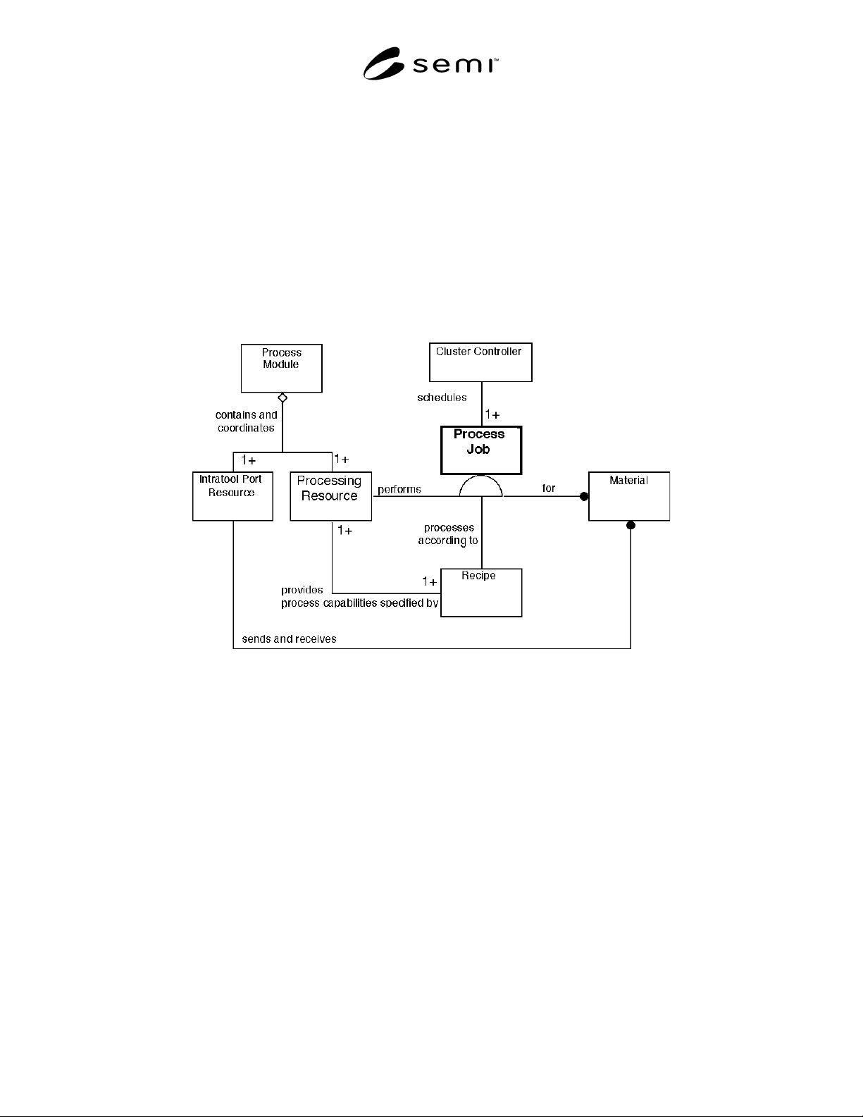
7.1.3 Material Processing Model — The material processing model in Figure 7 shows the use of the process job to
direct the processing resource to apply the appropriate process, as specified by the recipe, to one or more materials
in a process module. A processing resource in a process module has processing capabilities which are specified by
corresponding recipes.
Figure 7
Material Processing Information Model
A process job can control multiple material only if identical processing is applied to all. Processing should begin and
end simultaneously, synchronized with the arrival of the whole group of material.
The process job lifecycle extends beyond the active processing of the material. It exists from just before material
arrival at the intratool port resource, through setup and processing, and until just after the material departure at the
same, or another, intratool port resource. This allows for material-related pre-conditioning and post-conditioning of
the processing resource before the material is received and after it is sent. As material input and output is controlled
by the intratool port resource, it is the responsibility of the process module to ensure coordination of the intratool
port and processing resources.
This is the model used to establish the Processing Management definition. There is no standardization beyond
creation and control (starting, canceling, stopping, aborting, and pausing) of the high-level process job since the
low-level control of process modules is application-dependent.
There is a component of scheduling embodied in this model. The material, recipes, and processing resources are
scheduled by the cluster controller according to the process specification to a particular process module through the
use of the process job. In order to perform the required processing, material is transferred to the processing resource,
as directed by the cluster controller.