semi合集-English.pdf - 第79页
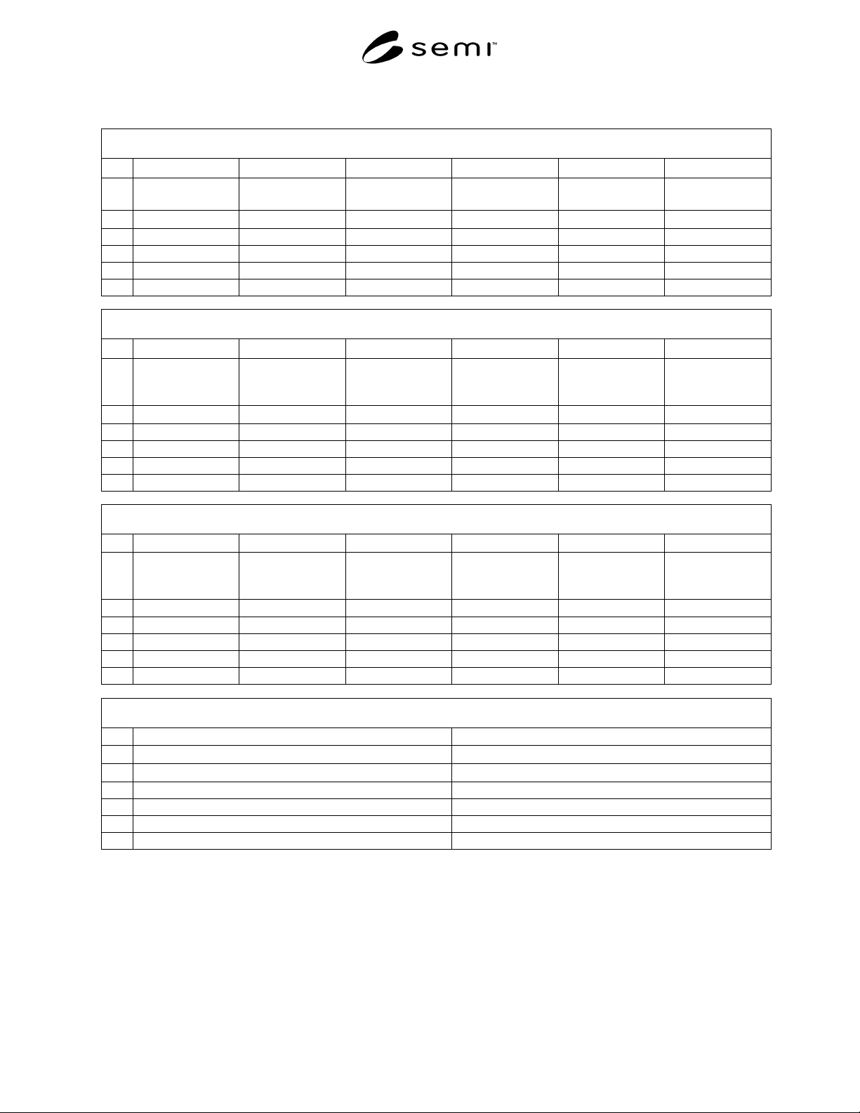
SEMI E6-0303 © SEMI 1982, 2003 25 Data Sheet 1000 – Exhaust (See SEMI E6 Sectio n 18) 1000 Exhaust A B C D E F 1 Equipment Component Exhaust Connection Number Connection Label on Equipment Utility Type Line Source Exhaus…

SEMI E6-0303 © SEMI 1982, 2003 24
byproducts that may come through the referenced
exhaust connection. In particular, identify any discharge
that might be regulated by the semiconductor
manufacturers’ discharge permit. For example: acid
condensates.
18.3.6 Minimum Static Pressure (1000G) — Enter the
minimum static pressure for the equipment to operate
correctly.
18.3.7 Maximum Static Pressure (1000H) — Enter the
highest static pressure for the equipment to operate
correctly.
18.3.8 Maximum Static Pressure Fluctuation (1000I)
— Enter the maximum negative static pressure change
during the processing cycle for the equipment to
operate correctly.
18.3.9 Idle Average Flow (1000J) — Enter the average
flow rate when the equipment is in idle condition.
18.4 Process Average Flow (1000K) — Enter the
average flow rate over the processing cycle.
18.5 Maximum Temperature (1000L) — Enter the
maximum exhaust temperature.
18.5.1 Equipment Component Fitting Size (1000M) —
Enter the fitting size of the connection provided on the
equipment component. In row 2 enter or select the units
of measure for the specified fitting size. For example:
mm or inches.
18.5.2 Equipment Component Fitting Size Dimension
(1000N) — Enter ID if fitting size in 100M is measured
as inner diameter. Enter OD if fitting size in 100M is
measured as outer diameter.
18.5.3 Equipment Component Fitting Material
(1000O) — Enter a general description of the fitting
material of the connection provided on the equipment
component. For example: Polypropylene.
18.5.4 Equipment Component Fitting Type (1000P) —
Enter the generic style of fitting of the connection
provided on the equipment component. Be sure to
include type and gender of the fitting. For example:
Collar, Flange, or Butt.
18.5.5 Flow Loss Coefficient, C (1000Q) — Enter the
flow loss coefficient (C). The flow loss coefficient can
be calculated by measuring the static pressure loss
through the equipment (SP), at the design flow rate, and
calculating velocity pressure (VP) as follows:
C = Flow loss coefficient (unit less) = SP/VP
Where:
SP = Static pressure loss through equipment (Pa)
VP = Velocity pressure (Pa) = ρV
2
/2
ρ = Air density (Kg/m
3
)
V = Air velocity (m/s)
18.5.6 External Damper Required (1000R) — Enter
yes if a balancing or isolation damper should be
provided by the equipment purchaser in the exhaust
system line that will be connected to the connection.
Enter no if a damper is not required or the equipment
supplier provides the damper with the equipment.
Clarify as required in the Exhaust Comments cell.
18.5.7 Drawing References (1000S) — Enter
references, such as drawing numbers, for any drawings,
schematics, instructions, jigs or fixtures showing this
connection. For example: connection template XXXXX
and P&ID YYYYY. Submit referenced material to
equipment purchaser with this data sheet.
18.5.8 Exhaust Comments (1000T) — Enter any
comments necessary to clarify information given for
this connection. For example: pressure switch will
alarm if exhaust static pressure falls below 0.5 inches
H
2
O. Also enter the design or test altitude so the
equipment user can make adjustments, as necessary, for
installation location altitude. For example: exhaust
requirements are based on equipment operation at sea
level.
SEMI E6-0303 © SEMI 1982, 2003 25
Data Sheet 1000 – Exhaust (See SEMI E6 Section 18)
1000 Exhaust
A B C D E F
1
Equipment
Component
Exhaust Connection
Number
Connection Label
on Equipment
Utility Type Line Source Exhaust Conveyed
Process Wastes
2
text text text text text text
3
4
5
6
1000 Exhaust
G H I J K L
1
Minimum Static
Pressure
Maximum Static
Pressure
Maximum Static
Pressure
Fluctuation
Idle Average Flow Process Average
Flow
Maximum
Temperature
2
Pa Pa Pa cmh cmh Degrees C
3
4
5
6
1000 Exhaust
M N O P Q R
1
Equipment
Component Fitting
Size
Equipment
Component Fitting
Size Dimension
Equipment
Component Fitting
Material
Equipment
Component Fitting
Type
Flow Loss
Coefficient
External Damper
Required
2
mm or inches ID or OD text text unit less yes or no
3
4
5
6
1000 Exhaust
S T
1 Drawing References Exhaust Comments
2
text text
3
4
5
6

SEMI E6-0303 © SEMI 1982, 2003 26
19 Other Data Sheets
19.1 Include data sheets or reference information for
any other connections such as connections for life
safety systems, gas detection systems, fire protection
systems, equipment control and communication
systems, material handling systems etc.
20 Related Documents
20.1 SEMI Standards
SEMI E36 — Semiconductor Equipment
Manufacturing Information Tagging Specification
SEMI E49.1 — Guide for Tool Final Assembly,
Packaging, and Delivery
SEMI E51 — Guide for Typical Facilities Services and
Termination Matrix
SEMI E72 — Specification and Guide for 300 mm
Equipment Footprint, Height, and Weight
SEMI E78 — Electrostatic Compatibility - Guide to
Assess and Control Electrostatic Discharge (ESD) and
Electrostatic Attraction (ESA) for Equipment
SEMI F34 — Guide for Liquid Chemical Pipe Labeling
SEMI F47 — Specification for Semiconductor
Processing Equipment Voltage Sag Immunity
SEMI S2 — Environmental, Health, and Safety
Guideline for Semiconductor Manufacturing Equipment
SEMI S8 — Safety Guidelines for Ergonomics
Engineering of Semiconductor Manufacturing
Equipment
20.2 Federal Standard
1
Federal Standard 209E — Airborne Particulate
Cleanliness Classes in Clean rooms and Clean Zones
20.3 ISO Standard
2
ISO 14644 – Cleanrooms and Associated Controlled
Environments – Part 1 Classification of Air Cleanliness
20.4 Other Documents
International SEMATECH 00043939ATR
3
— Utility
Measurement Protocol for Semiconductor Tools
1 General Service Administration, Federal Supply Service Bureau,
Specification Section, Suite 8167, 470 East L' Enfant Place SW,
Washington, D.C. 20407
2 International Organization for Standardization, ISO Central
Secretariat, 1, rue de Varembé, Case postale 56, CH-1211 Geneva 20,
Switzerland. Telephone: 41.22.749.01.11; Fax: 41.22.733.34.30
Website: http://www.iso.ch
3 SEMATECH, 2706 Montopolis Drive, Austin, TX 78741, website:
www.sematech.org
International SEMATECH 980134474ASTD — Guide
to Documenting Tool Accommodation Time and Cost
NOTICE: SEMI makes no warranties or
representations as to the suitability of the standards set
forth herein for any particular application. The
determination of the suitability of the standard is solely
the responsibility of the user. Users are cautioned to
refer to manufacturer’s instructions, product labels,
product data sheets, and other relevant literature
respecting any materials mentioned herein. These
standards are subject to change without notice.
The user’s attention is called to the possibility that
compliance with this standard may require use of
copyrighted material or of an invention covered by
patent rights. By publication of this standard, SEMI
takes no position respecting the validity of any patent
rights or copyrights asserted in connection with any
item mentioned in this standard. Users of this standard
are expressly advised that determination of any such
patent rights or copyrights, and the risk of infringement
of such rights, are entirely