semi合集-English.pdf - 第2231页
SEMI E58-0703 © SEMI 1997, 2003 12 # Current State Trigger Ne w State Action(s) Comment 6 UNSCHEDULED DOWNTIME All fault conditions have been clear ed. PRODUCTIVE Resume processing Transition 6 can only follow Transition…
SEMI E58-0703 © SEMI 1997, 2003 11
complete its normal cycle. If the operator intends to abort the process, then the process must be specifically aborted.
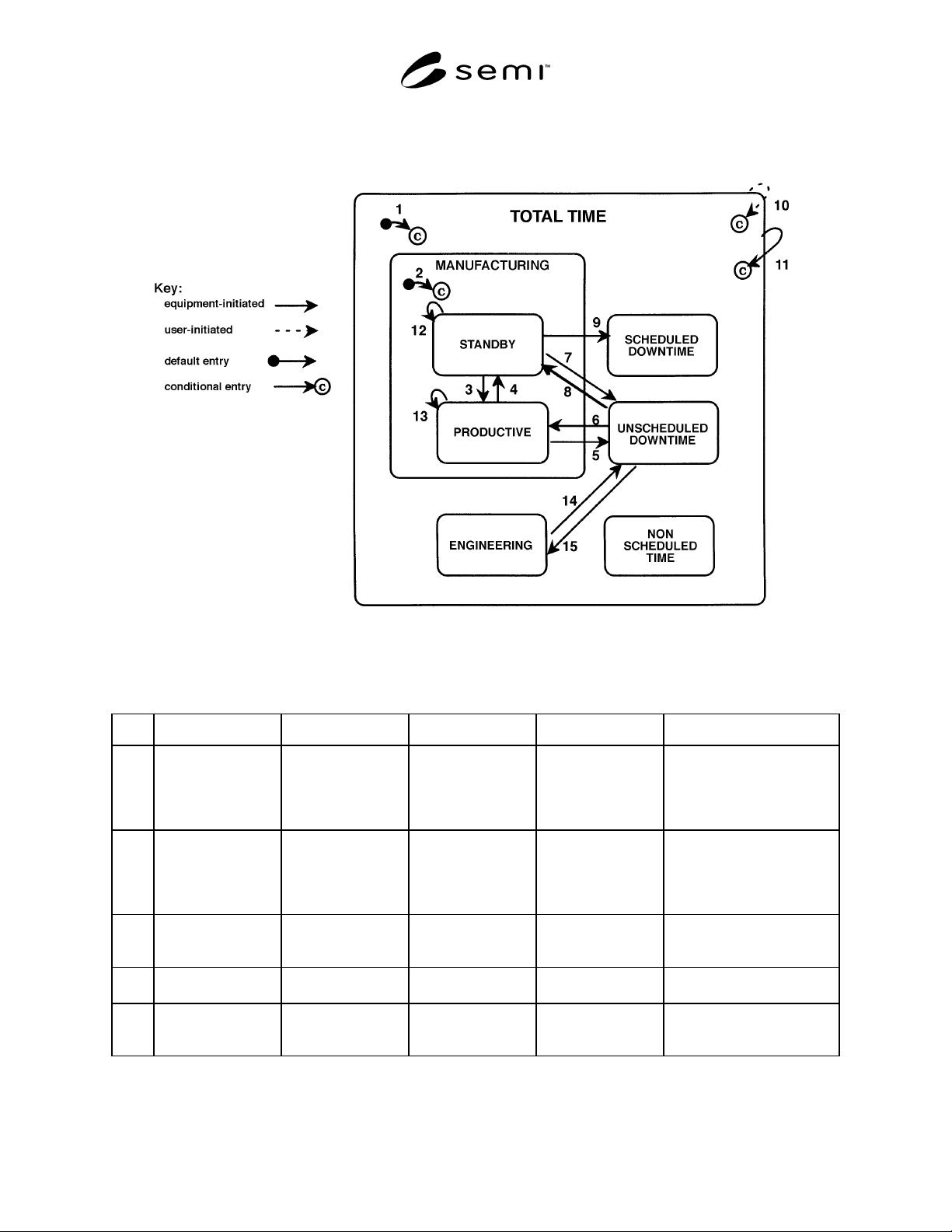
1.14.5.2 Table 1 defines the triggers for each transition shown in Figure 2.
Figure 2
ARAMS State Model
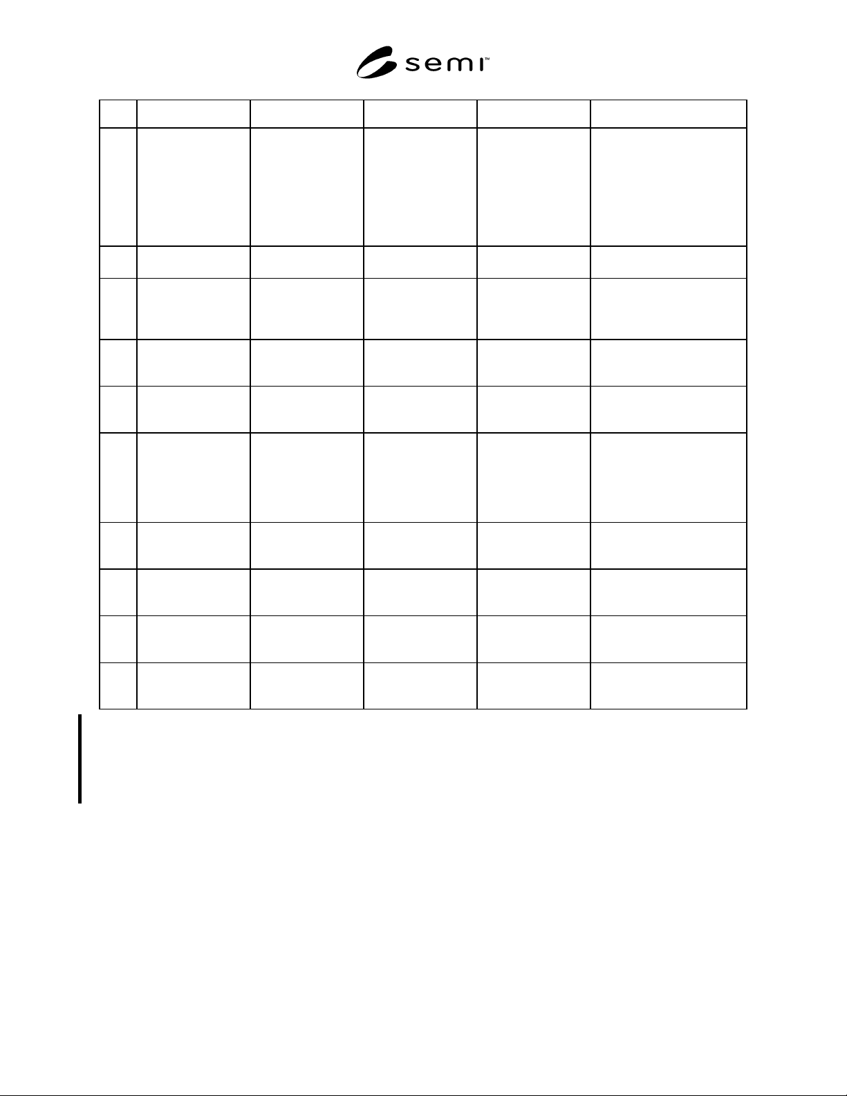
Table 1 Table 1 Transitions for ARAMS State Model
# Current State Trigger New State Action(s) Comment
1 (Either
undeterminable or
any state except
PRODUCTIVE or
STANDBY)
Powerup/reset Depends upon the
state in which
Transition 11
occurred (see Section
8.5.2).
None Entry state is dependent upon
previous state (see NOTE 1)
where this can be determined.
May not generate an event
report.
2 (any state) User selects a
manufacturing state.
PRODUCTIVE or
STANDBY,
depending upon the
status of the
equipment.
Determine the new
ARAMS
state/substate.
Equipment determines if
production criteria are
satisfied. If not, it transitions
to STANDBY. No event
report is generated.
3 STANDBY Equipment detects
that all its production
criteria are satisfied.
PRODUCTIVE Set ARAMSState to
value in PrdState
(Section 11.2).
May begin or resume
processing.
4 PRODUCTIVE Equipment detects a
standby condition.
STANDBY Monitor all
production criteria.
Equipment may detect a
standby condition at any time.
5 PRODUCTIVE Equipment detects an
exception.
UNSCHEDULED
DOWNTIME
Increment
InterruptionPrd
(Section 11.5).
Alarm or exception report
generated by same trigger.
SEMI E58-0703 © SEMI 1997, 2003
12
# Current State Trigger New State Action(s) Comment
6 UNSCHEDULED
DOWNTIME
All fault conditions
have been cleared.
PRODUCTIVE Resume processing Transition 6 can only follow
Transition 5. Automatic
recovery without operator
direction may be disabled by
the user. (See NOTE 2.) May
resume processing. Process
should be recoverable without
degradation.
7 STANDBY Equipment detects
fault condition.
UNSCHEDULED
DOWNTIME
None Alarm or exception report
generated by same trigger.
8 UNSCHEDULED
DOWNTIME
All fault conditions
have been cleared.
STANDBY Monitor all
production criteria.
Transition 8 can only follow
Transition 7 and may be
disabled by the user.
(See NOTE 3.)
9 STANDBY A monitored para-
meter has reached a
pre-defined limit.
SCHEDULED
DOWNTIME
None Preventive maintenance may
require reset of the monitored
parameter.
10 (Any ARAMS
state/substate)
User selects a new
ARAMS Substate
Code.
(Based on
state/substate selected
by user)
Depends upon
state/substate
selected.
The user may select a new
ARAMS state or substate at
any time.
11 (Any of the six basic
states)
Powerdown UNSCHEDULED
DOWNTIME,
SCHEDULED
DOWNTIME, or
NON-SCHEDULED
TIME.
None On powerup, the equipment
assumes this transition has
occurred. This state transition
does not represent a collection
event.
12 STANDBY Equipment detects a
change in standby
conditions.
STANDBY None Transitions 12 and 13 are
optional and may be disabled
by the user. (See NOTE 4.)
13 PRODUCTIVE Equipment detects a
change in productive
conditions.
PRODUCTIVE None Transitions 12 and 13 are
optional and may be disabled
by the user. (See NOTE 4.)
14 ENGINEERING Equipment detects a
fault condition.
UNSCHEDULED
DOWNTIME
None Transitions 14 and 15 may be
disabled by the user.
(See NOTE 5.)
15 UNSCHEDULED
DOWNTIME
All fault conditions
have been cleared.
ENGINEERING None Transition 14 shall only
follow Transition 15.
(See NOTE 6.)
NOTE 1: See the variable ARAMSState in Section 11.2.4.
NOTE 2: See PrdRecovery variable in Section 11.4.5.
NOTE 3: See SbyRecovery variable in Section 11.4.6.
NOTE 4: See SubstateSelect variable in Section 11.4.7.
NOTE 5: See EngInterrupt variable in Section 11.4.1.
NOTE 6: EngRecovery variable in Section 11.4.2 required for automatic recovery.
SEMI E58-0703 © SEMI 1997, 2003 13
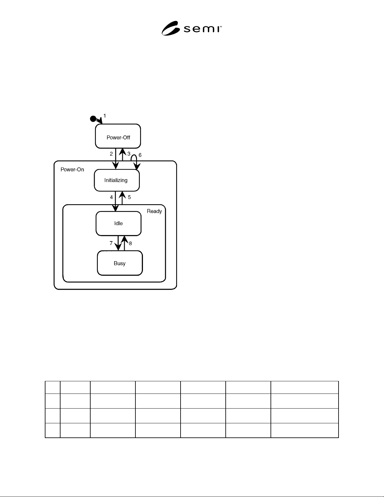
8.3 General Equipment Operations Model — The
equipment has various state models that it maintains in
addition to the ARAMS State Model. The state model
presented in this section (Figure 3) is provided as a
high-level example of one such model to clarify the
relationship between ARAMS and the equipment’s
operations. For purposes of ARAMS, it is referred to as
the General Equipment Operations Model.
Figure 3
Example of General Equipment Operations Model
1.14.6 ARAMS assumes that a similar model, either
formal or implicit, exists, although it may differ in
detail depending upon the equipment type and the
application. Formal implementation of the General
Equipment Operations Model is not required for
ARAMS compliance.
1.14.6.1 The states of the General Equipment
Operations Model are not SEMI E10 states or substates.
NOTE 12: To minimize confusion between references to
states and events, the events of losing power and recovering
power are termed powerdown and powerup respectively.
8.3.1 State Definitions — The General Equipment
Operations Model uses the following states:
8.3.1.1 POWER-OFF — The equipment has no power
and is unable to function. While this state is only valid
from a view external to the equipment, it is required to
cover all periods of time to match the ARAMS model.
8.3.1.2 POWER-ON — The POWER-ON state includes
all the functions of the equipment. It has two substates,
INITIALIZING and READY.
8.3.1.3 INITIALIZING — When equipment is first
powered on or recovers from a reset, it must initialize
its hardware and software subsystems and components,
including its different internal state models. This
process takes time, which is represented by the
INITIALIZING state.
8.3.1.4 READY — When all initializations are
complete, the equipment enters the READY state and is
able to interact with the user. The READY state has
two substates, IDLE and BUSY.
8.3.1.5 IDLE — In the IDLE state, the equipment is
inactive and able to accept a command for automatic
processing or manual operations.
NOTE 13: IDLE is not the same as the SEMI E10
STANDBY state. (See Section 8.5.3.)
8.3.1.6 BUSY — In the BUSY state, the equipment is
active. BUSY includes all operations of the equipment.
NOTE 14: BUSY is not the same as the SEMI E10
PRODUCTION state. (See Section 8.5.3.)
8.3.2 General Equipment Operations Model Table of
Transitions — Table 2 defines the triggers for each
transition shown in Figure 3. The second column,
labeled Table 1, shows the corresponding transition in
the ARAMS state model.
Table 2 Table 2 Table of Transitions for General Equipment Operations Model
# Table 1 Current State Trigger New State Action(s) Comment
1 None (undefined) Equipment is
installed.
POWER-OFF None New equipment
2 None POWER-OFF Power is turned on
(powerup).
INITIALIZING Begin system
initialization.
Initialization of hardware
and software.
3 11 POWER-ON Power is turned of
f
(powerdown).
POWER-OFF None Equipment does not
function.