semi合集-English.pdf - 第6415页
SEMI G75.2-069 8 © SEMI 1998 2 Figure 3 The Dimension o f the Table Figure 4 Exam ple of Push -Dow n Probe (40 Pin DIP L eadfra m e) 3 Test Condition 3.1 Adhesio n testing shall be carri e d o ut at the following ambient…
SEMI G75.2-0698 © SEMI 19981
SEMI G75.2-0698
TEST METHOD FOR MEASUREMENT OF ADHESIVE STRENGTH OF
LEADFRAME TAPE
1 Summary of Method
1.1 Two methods are described:
1.1.1 Pull-Up Method — Using a hook attached to a
tensile tester, the tape is pulled away from the
leadframe inner leads.
1.1.2 Push-Down Method — Using a probe attached to
a tensile tester, a leadframe inner lead is pushed away
from the tape.
1.2 The adhesive strength between the lead and the
tape should be measured at 23°C ± 5°C and 250°C.
2 Equipment
2.1 Tensile tester with appropriate load cell, clamping
chucks, and a chart recorder. Tensile tester shall keep
constant the traveling speed of clamping chucks, of
which the traveling distance can be read to the nearest 1
mm, and shall simultaneously record the load imposed
on the sample. It shall measure and record the imposed
load with ± 1% on a chart recorder.
2.2 Pull-Up Method
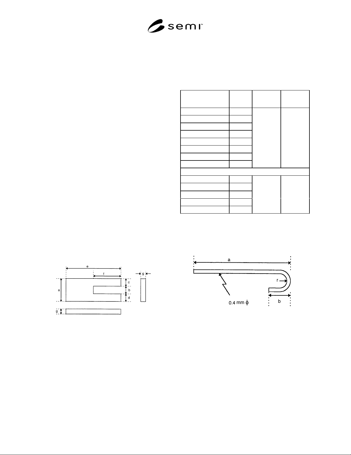
2.2.1 A clamp should be suitable for each leadframe
type. Example of the clamp design, for a typical 40 pins
DIP leadframe, is shown in Figure 1.
Figure 1
Example of Clamp Design
(40 Pins DIP Leadframe)
Table 1 Dimension and Material of Clamp and Hook
in Push-Up Method
Item/Dimension Value Material
Reference
Figure
Clamp
a 60 mm
b8 mm
c 26 mm
d 26 mm
e 60 mm
f 30 mm
g3 mm
Aluminum 1
Pull-Up Hook
φ
0.4 mm
a 100 mm
b5 mm
r 2.0 mm
Piano Wire 2
2.2.2 A pull-up hook should be suitable for each
leadframe type. Example of the pull-up hook, for a
typical 40 pins DIP leadframe, is shown in Figure 2.
Figure 2
Pull-Up Hook
(40 Pins DIP Leadframe)
2.3 Push-Down Method
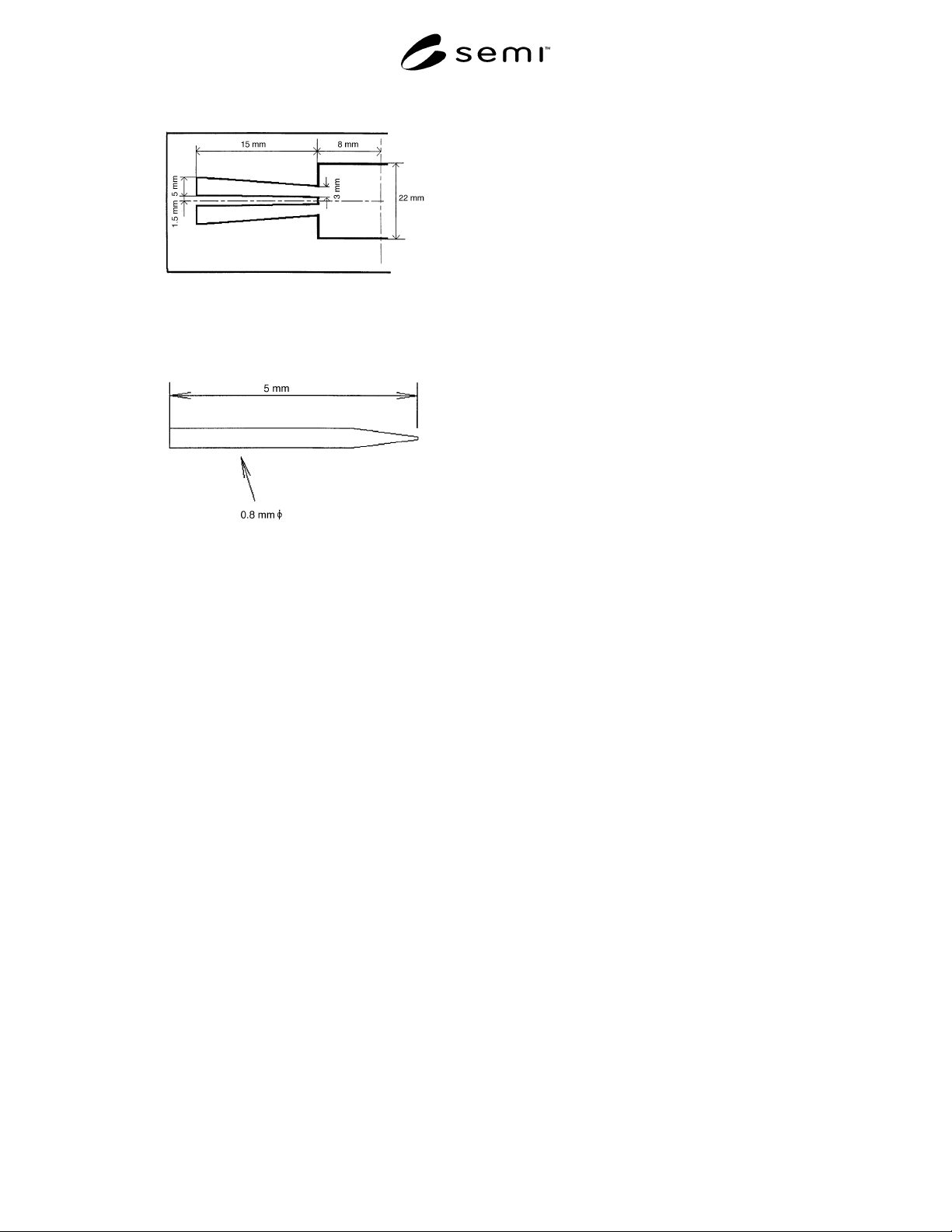
2.3.1 A table should be suitable for each leadframe
type. Example of the table, for a typical 40 pins DIP
leadframe, is shown in Figure 3.
2.3.2 A push-down probe should be suitable for each
leadframe. Example of the push-down probe, for a
typical 40 pins DIP leadframe, is shown in Figure 4.
SEMI G75.2-0698 © SEMI 1998 2
Figure 3
The Dimension of the Table
Figure 4
Example of Push-Down Probe
(40 Pin DIP Leadframe)
3 Test Condition
3.1 Adhesion testing shall be carried out at the
following ambient conditions:
Temperature — 23°C ± 5°C
Humidity — 50 ± 5% RH
4 Sampling
4.1 The sampling is one sample per one lot. The
vendor must report the definition of lot, if the customer
requires it.
5 Preparation of Specimens
5.1 Leadframe Manufacturers
5.1.1 Leadframes shall be taped using conditions for
temperature, pressure, and dwell-time agreed upon
between vendor and customer.
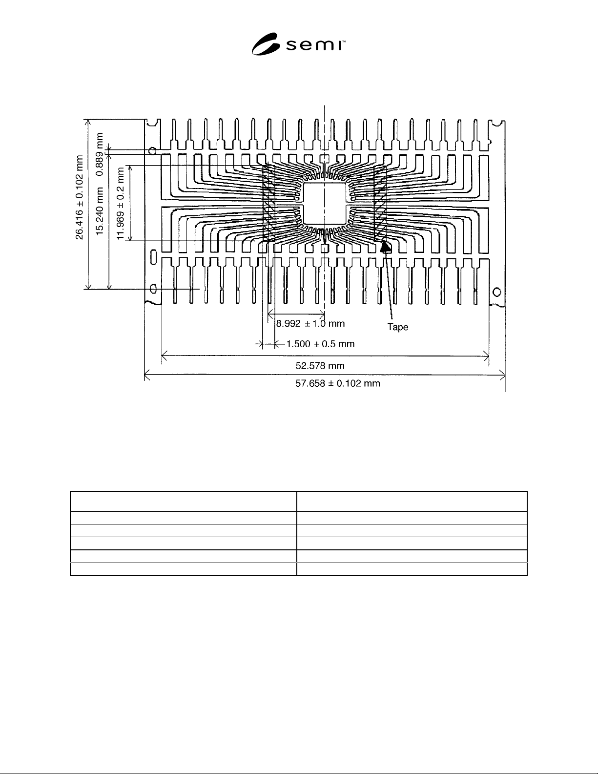
NOTE: A typical taped 40 pins DIP leadframe is shown in
Figure 5, and relevant information for this frame is shown in
Table 2.
SEMI G75.2-0698 © SEMI 19983
Figure 5
Typical Taped 40 Pin DIP Leadframe
Table 2 Relevant Information for 40 Pin DIP Leadframe
Leadframe Attribute Specification
Leadframe thickness 0.25 mm
Leadframe material Alloy 42
Leadframe manufacturing process Stamping
Plating None/Silver/Others
Surface treatment To be agreed upon between vendor and customer.
NOTE: The surface state of Alloy 42 is stable compared with Cu alloy which is oxidized easily.
6 Procedure
Hot adhesive strength at 250°C should be measured on the heater block with 60 ± 10 seconds.
6.1 Pull-Up Procedure
6.1.1 Set the tensile tester in the up-mode, and adjust the rate to 100 mm/minute.
6.1.2 Place the leadframe under the clamp as shown in Figure 6.