semi合集-English.pdf - 第63页
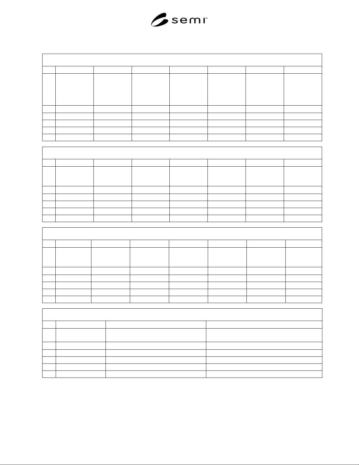
SEMI E6-0303 © SEMI 1982, 2003 9 Data Sheet 300 – Physical Charact eristics (See SEMI E6 Section 11) 300 Physical Cha racteristics A B C D E F G 1 Equipment Component Shipping and Receiving Information Reference Number o…

SEMI E6-0303 © SEMI 1982, 2003 8
11 Physical Characteristics Data Sheet
11.1 Include in Data Sheet 300, Physical
Characteristics the requested information for physical
attributes such as size, weight, layout, clearances, and
floor loading data.
11.2 Data Sheet 300, Physical Characteristics contains
the following items.
11.2.1 Equipment Component (300A) — Enter the
name of the equipment component for the data in this
row. The name should be the same name used in Data
Sheet 200.
11.2.2 Shipping and Receiving Information Reference
(300B) — Enter reference for document containing all
relevant shipping and receiving information. (See
Section 7.1.2 and Related Information 2.)
11.2.3 Number of Shipping Containers (300C) — Enter
the total number of containers or crates used to ship the
equipment and all supplier provide support equipment.
11.2.4 Move-in, Placement and Assembly Instructions
Reference (300D) — Enter reference for document
containing all installation instruction. (see Section 7.1.3
and Related Information 3.)
11.2.5 Number of Cleanroom Move-in Pieces (300E)
— Enter the total number of pieces of equipment to be
moved into the manufacturing cleanroom.
11.2.6 Biggest Move-in Piece Length, Width, Height,
Weight (300F, 300G, 300H, 300I) — Enter the size and
weight of the largest single move-in piece of the
equipment.
11.2.7 Installation ESH Information Reference (300J)
— Enter reference for document containing all relevant
environmental, safety, and health information related to
equipment installation. (See related SEMI Safety
Guidelines)
11.2.8 Assembled Length, Width, Min. Height, Max
Height, Weight (300K, 300L, 300M, 300N): 300O) —
Enter the size and weight of the equipment component.
Minimum and maximum height should include travel of
any provided leveling feet.
11.2.9 Operational Clearance Front, Right, Left, Back,
Top Bottom (300P, 300Q, 300R, 300S, 300T) 300U) —
Enter the operational clearances on all sides of
equipment necessary for safety, operation, and
maintenance. (Right and left should be as viewed from
the front)
11.2.10 Floor Loading Diagram Reference (300V) —
Enter the reference for the floor-loading diagram
showing the static weight loads at each equipment
support point.
11.2.11 Drawing References (300W) — Enter
references, such as drawing numbers, for any drawings,
schematics, instructions, jigs or fixtures showing
equipment. For example: Equipment Footprint Drawing
YYYYY. Submit referenced material to equipment
purchaser with this data sheet.
NOTE 6: Information regarding 300mm equipment may be
found in SEMI E72 and SEMI E63.
11.2.12 Physical Conditions Comments (300X) —
Enter any comments necessary to clarify or add to
information given for this equipment component.
SEMI E6-0303 © SEMI 1982, 2003 9
Data Sheet 300 – Physical Characteristics (See SEMI E6 Section 11)
300 Physical Characteristics
A B C D E F G
1
Equipment
Component
Shipping and
Receiving
Information
Reference
Number of
Shipping
Containers
Move-in,
Placement and
Assembly
Instructions
Reference
Number of
Cleanroom
Move-in Pieces
Biggest Move-in
Piece Length
Biggest Move-in
Piece Width
2
text text # text # mm mm.
3
4
5
6
300 Physical Characteristics
H I J K L M N
1
Biggest Move-in
Piece Height
Heaviest Move-
in Piece
Weight
Instillation ESH
Information
Reference
A
ssembled
Length
A
ssembled
Width
Minimum
A
ssembled
Height
Maximum
A
ssembled
Height
2
mm kg text mm mm mm mm
3
4
5
6
300 Physical Characteristics
O P Q R S T U
1
Assembled
Weight
Operational
Clearance Front
Operational
Clearance Right
Operational
Clearance Left
Operational
Clearance Back
Operational
Clearance Top
Operational
Clearance
Bottom
2
kg mm mm mm mm mm mm
3
4
5
6
300 Physical Characteristics
V W X
1
Floor Loading
Diagram Reference
Drawing References Physical Characteristics Comments
2
text text text
3
4
5
6

SEMI E6-0303 © SEMI 1982, 2003 10
12 Electrical Power Data Sheet
12.1 Include in Data Sheet 400, Electrical Power the
requested information for equipment connections to
facilities systems including but not limited to electrical
power distribution and conditioning systems.
12.2 Data Sheet 400, Electrical Power contains the
following items.
12.2.1 Equipment Component (400A) — Enter the
name of the equipment component where the
connection is located. The name should the same name
used in Data Sheet 200 and 300. For example:
Mainframe, Vacuum Pump, or Chiller.
12.2.2 Electrical Power Connection Number (400B) —
Enter a unique connection number for every utility
connection. For example: 401, 402, 403, and so on.
12.2.3 Connection Label on Equipment (400C) —
Enter the name found on the label that identifies this
physical connection on the equipment. For example
input power or power ground.
12.2.4 Utility Type (400D) — Enter the name of
electrical service to be provided through the connection.
Examples: Normal Power, Conditioned Power,
Uninterruptible Power, Standby Power and Emergency
Power. If selection is not Normal Power, specify reason
in Electrical Power Comments cell.
12.2.5 Line Source (400E) — Identify the source of the
supply line for this connection. If the line comes from a
provided component covered in the data sheets enter the
connection number(s) at the other end of the line. If the
line comes from a facilities source enter facilities
system. For example: 403 or facilities system.
12.2.6 Voltage/Phase/Wire (400F) — Enter the
necessary voltage, number of phases, and number of
wires for the component connection. Ground wires will
be designated separately. For example: 480V/3 Phase/4
Wire + ground or 120V/1 Phase/2 Wire + ground.
12.2.7 Frequency (400G) — Enter the power frequency
of electrical service specified.
12.2.8 Equipment Component Connection Type (400H)
— Enter the method of connection to the component
and a description of the connection on the equipment.
Include the appropriate code (such as NEMA, CEE,
CEI, or ICE), suffix for plug connection, and lug
type/size for hardwire connection. For examples: Plug
NEMA 20P or Hardwire mechanical lug/#6-#2 wire per
phase.
12.2.9 Ampere Interrupting Capacity (400I) — Enter
the ampere interrupting capacity (AIC) rating.
12.2.10 Full Load Amps Phase A, B, C, Neutral (400J,
400K, 400L, 400M) — Enter the nameplate full load
amperage rating for the electrical utility connection,
voltage, and frequency.
12.2.11 Branch Circuit Protection (400N) — Enter the
supplier recommended fuse or breaker setting necessary
to protect the branch circuit supplying power to the
equipment connection.
12.2.12 Real Power Idle Average (400O) — Enter the
average true real power demand for the equipment idle
condition. Real power is the time average of the
instantaneous product of voltage and current. Real
power is expressed in Watts.
12.2.13 Real Power Process Average (400P) — Enter
the average true real power demand for the equipment
processing cycle.
12.2.14 Real Power Maximum (400Q) — Enter the
maximum one second average true real power demand
(value for equipment processing cycle or idle condition,
whichever is greater).
12.2.15 Apparent Power Idle Average (400R) — Enter
the average true RMS apparent power demand for the
equipment idle condition. Apparent power is the
product of RMS volts and RMS amps. Apparent power
is expressed in VA, volt-amps.
12.2.16 Apparent Power Process Average (400S) —
Enter the average true RMS apparent power demand for
the equipment processing cycle.
12.2.17 Apparent Power Maximum (400T) — Enter the
maximum one second average true RMS apparent
power demand (value for the equipment processing
cycle or idle condition, whichever is greater).
12.2.18 Current Idle Average Phase A, B, C, Neutral -
(400U, 400V, 400W, 400X) — Enter the average true
RMS current for the equipment idle condition.
12.2.19 Current Process Average Phase A, B, C,
Neutral (400Y, 400Z, 400AA, 400AB) — Enter the
average true RMS current for the equipment processing
cycle.
12.2.20 Current Maximum Phase A, B, C, Neutral
(400AC, 400AD, 400AE, 400AF) — Enter the
maximum one second average true RMS current (value
for equipment processing cycle or idle condition,
whichever is greater).
12.2.21 Current THD Phase A, B, C, Neutral (400AG,
400AH, 400AI, 400AJ) — Enter the true RMS current
Total Harmonic Distortion (THD) value that is time
coincident with the reported Apparent Power Maximum
value.