semi合集-English.pdf - 第6157页
SEMI G33-90 © SEMI 198 6, 1996 2 combination of metals is applied to a suitable substrate and fi red. rundown — T he vertical extension of metallization from the ceram ic (see Figure 2). seal area — A dimens ional outlin…

SEMI G33-90 © SEMI 1986, 19961
SEMI G33-90
SPECIFICATION FOR PRESSED CERAMIC PIN GRID ARRAY
PACKAGES
1 Preface
This specification defines the acceptance criteria for
ceramic pin grid array packages produced using pressed
ceramic, mechanically inserted pins and solder for
electrical interconnection of pins.
2 Applicable Documents
2.1 ANSI Specification
1
Y14.5 — Dimensioning and Tolerancing
2.2 ASTM Specification
2
B 152 — Copper Metal Specification
2.3 Federal Specification
3
QQ-N-290A — Nickel Plating
QQ-S-571E — Solder-Alloy Compositions
2.4 Military Specifications
3
MIL-STD-105 — Sampling Procedures and Tables for
Inspection by Attributes
MIL-STD-883 — Test Methods and Procedures for
Microelectronics
MIL-G-45204 — Gold Plating, Electrodeposited
MIL-M-38510 — General Specification for
Microcircuits
2.5 JEDEC Specification
4
Pub. No. 95 — Registered and Standard Outlines for
Semiconductor Devices
3 Selected Definitions
blister (bubble) ceramic — Any separation within the
ceramic which does not expose underlying ceramic
material.
blister (bubble) metal — Any localized separation
within the metallization or between the metallization
and ceramic which does not expose underlying
metallization or ceramic material.
1 ANSI, 1430 Broadway, New York, NY 10018
2 American Society of Testing and Materials, 100 Barr Harbor Drive,
West Conshohoken, PA 19428-2959
3 Military Standards, Naval Publications and Form Center, 5801
Tabor Avenue, Philadelphia, PA 19120
4 JEDEC, 2001 Eye Street N.W., Washington, D.C. 20006
burr — An adherent fragment of excess parent material
at the component edge.
chip — A region of ceramic missing from the surface or
edge of a package which does not go completely
through the package. Chip size is given by its length,
width and depth from a projection of design planform
(see Figure 1).
crack — A cleavage or fracture that extends to the
surface of a package which may or may not pass
through the entire thickness of the package.
contact pad — That metallized pattern that provides
mechanical or electrical connection to the external
circuitry.
die attach surface — A dimensional outline designated
for die attach.
dielectric — A material applied to the surface of a
package which provides such functions as electrical
insulation, passivation of underlying metallization and
limitation of solder flow.
discoloration — Any change in the color of the
package metallization as detected by the unaided eye.
flatness — The allowable deviation of a surface from a
reference plane. The tolerance zone is defined by two
parallel planes within which the surface must lie.
footprint — Pin pattern.
foreign material — An adherent particle other than
parent material.
isolation gap — Metal-free space between conductive
areas.
peeling (flaking) — Any separation of metallization
from the base material exposing the base material.
pit — Any unspecified depression in the package.
post-metallization — The process by which
metallization is applied to a body (substrate) after the
body has been fully sintered.
projection — An adherent fragment of parent material
on the package surface.
pullback — The linear distance between the edge of the
ceramic and the first measurable metallization and/or
glass interface (see Figure 2).
refractory metallization — The process by which a high
melting point (typically in excess of 1800°C) metal or

SEMI G33-90 © SEMI 1986, 1996 2
combination of metals is applied to a suitable substrate
and fired.
rundown — The vertical extension of metallization
from the ceramic (see Figure 2).
seal area — A dimensional outline area designated to
provide a surface for sealing.
seating plane — Defined by the standoff features or the
package base plane if no standoff is used (see Figure 3).
SLAM — Abbreviation for “Single Layer Alumina
Metallization,” which denotes a package design without
a physical die attach cavity.
solder — An alloy with a melting point equal to or less
than 427°C.
standoff — The designed separation between the base
plane and the seating plane created by a physical
feature. Standoff use, configuration, and placement is
optional (see Figure 3).
terminal — Case outline at point of entry or exit of an
electrical contact.
thick film metallization — The process by which a thin
layer of metal (usually in the 0.3 to 1.0 µm range) is
applied to a suitable substrate by methods including
sputtering, vacuum evaporation and chemical vapor
deposition.
TIR — Total Indicator Reading.
window frame — A separate member of ceramic which
is joined to the surface of the package on which a flat
lid is attached for sealing.
4 Ordering Information
Purchase orders for pin grid array packages furnished to
this specification shall include the following items:
1. Drawing number and revision level
2. Certification requirements
3. Quantity
4. Reference to this document
5. Any exceptions to print or specifications
5 Dimensions and Permissi ble Variations
The dimensions of the pin grid array package shall
conform to SEMI Standards or to the customer
drawing, and be within the outline of the appropriate
JEDEC standard.
6 Material Parameters
The definitions, defects, and functional testing
described in this specification relate directly to a
nominal package made with the following materials.
They may also be applicable to similar pin grid array
packages made with other materials.
6.1 Ceramic Properties
6.1.1 Materials — Alumina content 90% minimum.
Beryllia content to be in excess of 98.5% BeO.
6.1.2 Color — Dark or white.
6.2 Metal Properties
6.2.1 Plating
6.2.1.1 Plating finish shall be per MIL-M-38510;
Nickel Plating (if designated) shall be per QQ-N-290A,
50 µ"–350 µ" (0.1300 mm–0.08890 mm). Gold plating
(if desired) shall conform to MIL-G-45204, Type III
and 50 µ"–225 µ" (0.1300 mm–0.05080 mm).
6.2.2 Metallization
6.2.2.1 Metallized circuits and areas can be thick film,
thin film or refractory post-metallized. Such
metallization materials may be, but are not limited to,
the following:
1. Thick Film Materials
a. Gold (Au) and Gold Alloys
b. Silver (Ag)
c. Silver - Platinum - Palladium (AgPtPd)
d. Silver - Palladium - Platinum (AgPdPt)
e. Copper (Cu)
2. Thin Film Materials
a. Copper (Cu)
b. Chromium (Cr)
c. Nickel (Ni)
d. Titanium (Ti)
4. Refractory Materials
a. Molybdenum - Manganese (MoMn)
b. Molybdenum - Tungsten (MoW)
6.2.3 Solder — Solder compositions used in the
manufacture of pressed ceramic pin grid array packages
shall include, but not be limited to, the following, per
QQ-S-571E:
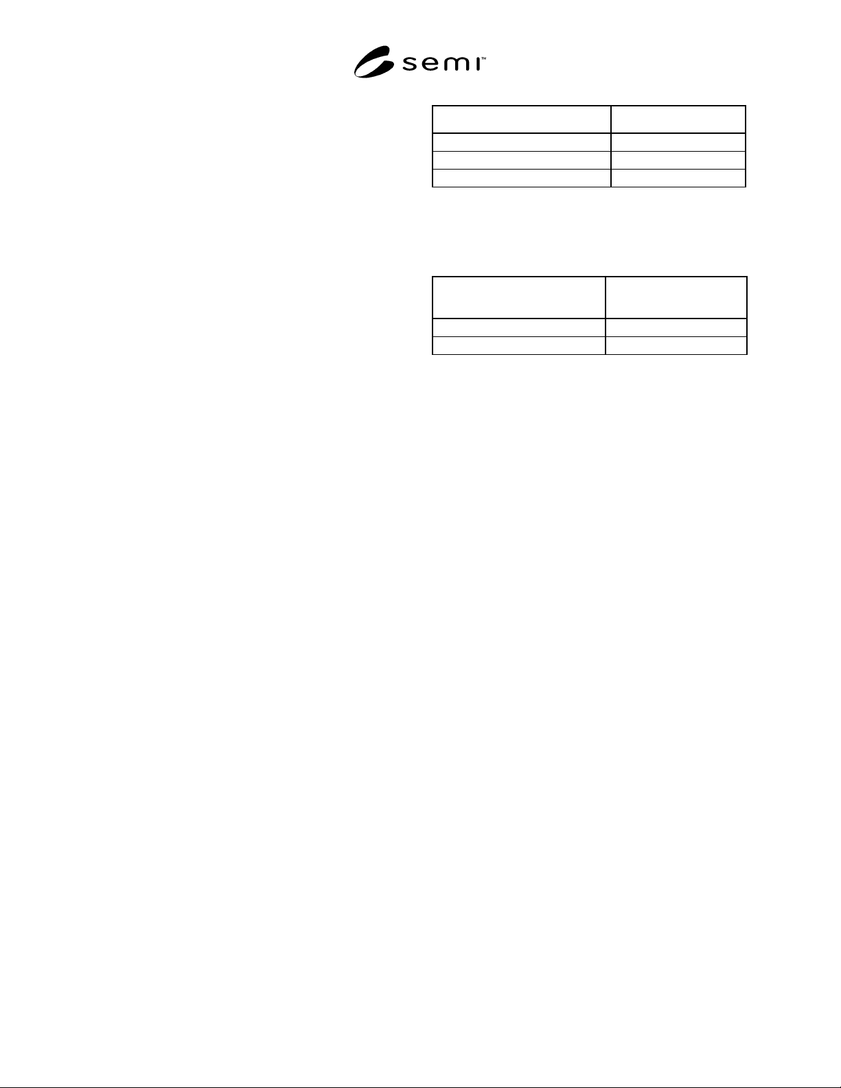
1. 10/90 — 10% Sn/90% Pb
SEMI G33-90 © SEMI 1986, 19963
2. 63/37 — 63% Sn/37% Pb
3. 10/88/2 — 10% Sn/88% Pb/2% Ag
6.2.4 Pin Material — CDA150, OFHC Copper,
Zirconium alloy per ASTM B 152.
6.3 Thick Film Dielectric — An amorphous or
polycrystalline glass or approved equivalent ranging in
thickness from 0.013 mm (0.0005") to 0.038 mm
(0.0015").
7 Defect Limits
A magnification of 10× shall be used to inspect the
packages unless otherwise specified.
7.1 Ceramic
7.1.1 Cracks — Per MIL-STD-883, Method 2009.
7.1.2 Chips — (See Figure 1.)
7.1.2.1 General
7.1.2.1.1 Corner — Chips shall not exceed 0.762 mm
(0.030") length × 0.762 mm (0.030") width × 0.762 mm
(0.030") depth (see Figure 1-B).
7.1.2.1.2 Edge — Chips shall not exceed 1.52 mm
(0.060") length × 0.635 mm (0.025") width × 0.635 mm
(0.025") depth (see Figure 1-A).
7.1.2.1.3 Chips cannot encroach upon contact pad or
penetrate metallization.
7.1.2.2 Seal Area
7.1.2.2.1 Design With Window Frame — Chips shall
not exceed 0.635 mm (0.025") length × 0.635 mm
(0.025") width × 0.635 mm (0.025") depth maximum.
Chips cannot reduce the seal area width by more than
1/3 of the design width.
7.1.2.2.2 Design Without Window Frame — See
Section 7.5 of this specification for dielectric inspection
criteria.
7.1.2.3 Cavity Edges
7.1.2.3.1 Chips in the edges around the cavity shall not
exceed 0.381 mm (0.015") along the edges or 0.127
mm (0.005") in depth.
7.2 Package Flatness — 0.004 inch/inch maximum
7.2.1 Seal Area Flatness
7.2.1.1 With Window Frame
Seal Area Size Seal Area Flatness (TIR)
0–12.7 mm (0.000"-0.500") 0.051 mm (0.002") MAX
12.72–19.05 mm (0.501"-0.750") 0.076 mm (0.003") MAX
19.07 mm & greater (0.751") 0.101 mm (0.004") MAX
7.2.1.2 Without Window Frame — Flatness shall be
0.004" per inch maximum TIR.
7.2.2 Die Attach Area Flatness
Die Attach Area Size
Die Attach Area Flatness
(TIR)
0–12.7 mm (0.000"-0.500") 0.051 mm (0.002") MAX
12.72–19.05 mm (0.501"-0.750") 0.088 mm (0.0035") MAX
7.3 Metallization Misalignment (see Figure 2)
7.3.1 Metallization Rundown — For the internal cavity
shall not exceed 25% of the cavity depth, with a
minimum of 0.127 mm (0.005") minimum isolation
required.
7.3.2 Wire Bond Finger Pullback — 0.254 mm
(0.010") maximum.
7.3.3 Wire Bond Finger Rundown — Not to exceed
1/3 of the ceramic cavity depth; 0.127 mm (0.005")
isolation required.
7.3.4 Pattern Isolation — Dimension shall not be
reduced by more than 50% of the design.
7.4 Metallization Voids
7.4.1 Wire Bond Finger — Must be free of voids or
bare spots in the bonding area as defined by customer
drawing.
7.4.2 Die Attach Surface
7.4.2.1 SLAM Design — Three voids are allowed, with
a maximum of 0.127 mm (0.005") diameter separated
by a distance greater than 0.254 mm (0.010"). Voids
within 0.254 mm (0.010") of perimeter of die attach
print area shall not be considered as the basis for
rejection.
7.4.2.2 Cavity Design — Three voids are allowed with
a maximum of 0.254 mm (0.010") diameter separated
by a distance greater than 0.254 mm (0.010"). Voids
within 0.381 mm (0.015") of die attach cavity wall shall
not be considered as the basis for rejection.
7.4.3 Solder
7.4.3.1 Pin Coating — Solder wetting acceptability
shall be per criteria in MIL-STD-883, Method 2003.