semi合集-English.pdf - 第4396页
SEMI F97-0305 © SEMI 2005 6 7 Ordering Information 7.1 Whe n integrati ng FPUs into a FM CS, suppliers and purchasers ha ve to agree on details on how the i ntegration will be performed. Th is includes a number of items …
SEMI F97-0305 © SEMI 2005 5
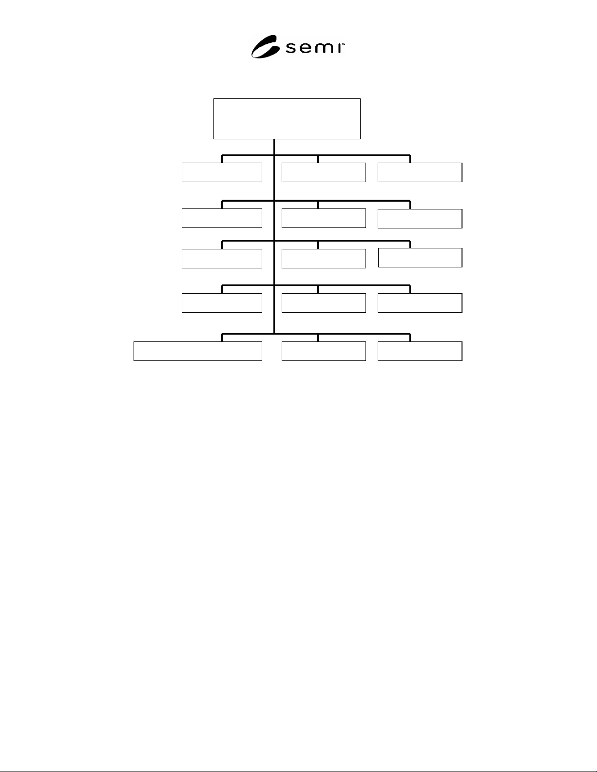
6.1.2 Figure 2 depicts typical examples of Facility Package Units.
Facility Monitoring and
Control System
Cleanroom
Electrical
Building systems
HVAC
Chilled water
Exhaust
Hot water
Fire protectionCompressed air
Ultra pure water
Chemicals
Gases
Waste water treatment
...
Life safety
Facility Monitoring and
Control System
Cleanroom
ElectricalElectrical
Building systems
HVAC
Chilled water
Exhaust
Hot waterHot water
Fire protectionFire protectionCompressed airCompressed air
Ultra pure water
ChemicalsChemicals
GasesGases
Waste water treatment
......
Life safetyLife safety
Figure 2
Typical Examples of Facility Package Units
6.1.2.1 Description of Figure 2.
Building systems — facility installation concerning the building, e.g. lighting.
Chemicals — facility installation for the supply of chemicals, e.g. for process tools.
Chilled water system — facility installation for the supply of cold water, e.g. for air condition or process tools.
Cleanroom — production area with clean conditions and specifications concerning air condition.
Compressed air — facility installation for the supply of compressed air.
Electrical — facility installation for the electrical power supply.
Exhaust — facility installation for the disposal of gases and contaminated air.
Fire protection — facility installation for fire protection, e.g. for fire and smoke detection.
Gases — facility installation for the supply of bulk or special gases, e.g. for process tools.
Hot water — facility installation for the supply of hot water, e.g. for radiators, air condition or process tools.
HVAC — facility installation for heating, ventilation and air conditioning.
Life safety — facility installation for life safety and security, e.g. for detection of leakages of gases.
Ultra pure water — facility installation for the supply of ultra pure water, e.g. for process tools.
Waste water treatment — facility installation for the treatment of waste water.
SEMI F97-0305 © SEMI 2005 6
7 Ordering Information
7.1 When integrating FPUs into a FMCS, suppliers and purchasers have to agree on details on how the integration
will be performed. This includes a number of items such as the information to be exchanged between FMCS and
FPUs, the communication protocol to be used
2
, or details of the available FPU subcontrol level. Other parties such
as fab planners or system integrators may be involved in this information exchange. Related Information 2 provides
a template for the ordering information and examples for its use.
8 Conventions
8.1 This standard follows the conventions for state model methodology and service definitions as defined by other
SEMI standards supplemented by specific extensions. The conventions used in this standard are described in the
following paragraphs.
8.2 State Model Methodology
8.2.1 This document uses the state model methodology as defined within SEMI E30 to describe the behavior of
FPUs. A state model is comprised of the following elements:
definitions of each state and sub state,
a diagram of the states and the transition between states, and
a state transition table.
8.2.2 The diagram of the state model uses the Harel State Chart notation
3
.
8.3 Notion of Alarm-Mode, Warning-Mode, Error-Mode — Signifies the importance of the situation that occurred at
the FPU to draw attention at the FMCS. Error-Mode is generally used to signify an error. This error may be
persistent for some time until the error situation is corrected. Warning-Mode may be used to signal a higher
awareness that is to be raised at the FMCS. Again, attention may be needed to correct the problem. Alarm-Mode
signals the highest awareness required and may again need some attention for correction. The use of which mode is
used when and where is intentionally left to the agreement between the purchaser and the supplier. It is
recommended to use always the same philosophy for use of these three modes for the entire facility when possible.
8.4 Transition Tables
8.4.1 Transition Tables are provided in conjunction with the state diagrams to explicitly describe the nature of each
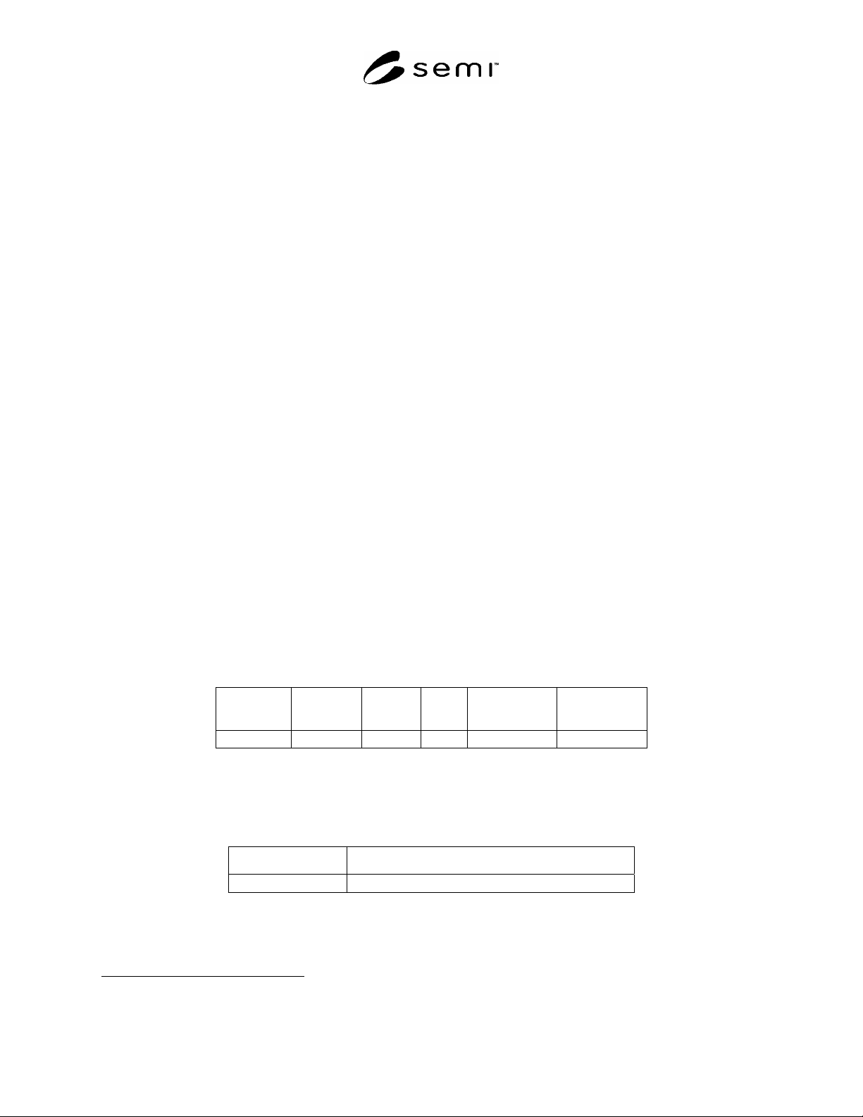
state transition. A transition table contains columns for transition number, previous state, trigger, new state, actions
and a remark. The trigger for the transition occurs while in the previous state. The actions include a combination of
actions taken upon exit of the previous state and actions taken upon entry into the new state.
Number Previous
State
Trigger New
State
Actions Remark
8.5 Operation Representation
8.5.1 Operations are used to describe interfaces between different resources (e.g. interfaces between FMCS and
FPUs). An operation definition table defines the specific set of operations for a specific resource as shown in the
following table:
Operation Description
8.5.2 Operation — Defines the operation name. The operation name has to be unique for each given resource.
8.5.3 Description — Gives a short comprehensive description of the operation with regard to functionality.
2 As an example, OPC Data Access combined with the agreed communications protocol may be used for interconnecting FMCS and FPUs.
3 Harel, D., "Statecharts: A Visual Formalism for Complex Systems", Science of Computer Programming 8 (1987), p. 231-274
SEMI F97-0305 © SEMI 2005 7
8.6 Parameter Definitions
8.6.1 When calling an operation, parameters can be passed and returned. Parameters to be passed and returned
depend upon the operation that is called. By using a parameter definition table the parameters passed and returned
by an operation are defined.
Parameter Description Direction Data Type
8.6.2 Parameter — Within the parameter column the name of the specific parameter is given.
8.6.3 Description — Contains a description of a parameter.
8.6.4 Direction — Defines the direction:
FMCS -> FPU: originated by FMCS and received by FPU
FPU -> FMCS: originated by FPU and received by FMCS
8.6.5 Data Type — Defines the format of a parameter.
8.7 Field Definitions
8.7.1 A parameter can consist of different fields that define the contents of a parameter. A field definition table
defines the format of the fields maintained within a specific parameter.
Field Bit Meaning Mandatory/optional
8.7.2 Field — A parameter can consist of different fields representing the contents of a parameter. Within the field
column the name of the specific field is given.
8.7.3 Bit — In case a field is stored within a bitwise-formatted parameter, the bit column defines the bit number or
bit range where the field value is stored.
8.7.4 Meaning — Defines the meaning of the one or several field values.
8.7.5 Mandatory/Optional — Defines if setting the value of a field is either mandatory or optional.
9 Requirements
9.1 Interconnection between FMCS and FPUs
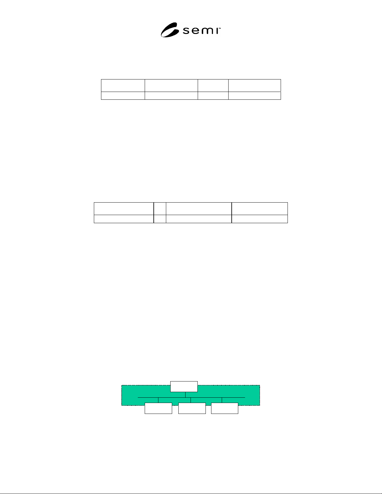
9.1.1 The interconnection between the FMCS and the FPUs may be made by any type of bus system specified by
SEMI (e.g. SEMI E54 series) as well as industrial ethernet based networks. It is the purpose of this standard:
to specify the semantics of the services that are exchanged between the FMCS and the FPUs, and
to model the status information of the state machines that are maintained by the FPUs.
9.1.2 As introduced in §7, state models are used to represent the current state of a FPU. The FMCS may use this
state information in order to display the state of all FPUs. In addition, the FMCS may decide based on the state of a
FPU whether remote operations on a FPU are advisable or not.
FMCS
FPU 1 FPU 2 FPU n
FMCS
FPU 1 FPU 2 FPU n
Figure 3
Interconnection Between FMCS and FPUs